2004 NISSAN TERRANO Location
[x] Cancel search: LocationPage 1287 of 1833
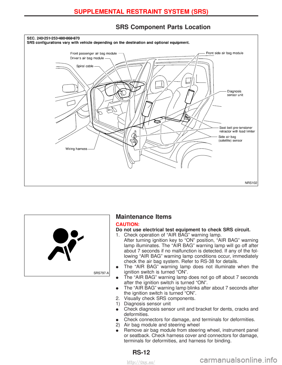
SRS Component Parts Location
Maintenance Items
CAUTION:
Do not use electrical test equipment to check SRS circuit.
1. Check operation of ªAIR BAGº warning lamp.After turning ignition key to ªONº position, ªAIR BAGº warning
lamp illuminates. The ªAIR BAGº warning lamp will go off after
about 7 seconds if no malfunction is detected. If any of the fol-
lowing ªAIR BAGº warning lamp conditions occur, immediately
check the air bag system. Refer to RS-38 for details.
I The ªAIR BAGº warning lamp does not illuminate when the
ignition switch is turned ªONº.
I The ªAIR BAGº warning lamp does not go off about 7 seconds
after the ignition switch is turned ªONº.
I The ªAIR BAGº warning lamp blinks after about 7 seconds after
the ignition switch is turned ªONº.
2. Visually check SRS components.
1) Diagnosis sensor unit
I Check diagnosis sensor unit and bracket for dents, cracks and
deformities.
I Check connectors for damage, and terminals for deformities.
2) Air bag module and steering wheel
I Remove air bag module from steering wheel, instrument panel
or seatback. Check harness cover and connectors for damage,
terminals for deformities, and harness for binding.
NRS102
SRS797-A
SUPPLEMENTAL RESTRAINT SYSTEM (SRS)
RS-12
http://vnx.su/
Page 1342 of 1833
Checking Body Corrosion
Visually check the body sheet metal panel for corrosion, paint damage (scratches, chipping, rubbing, etc.) or
damage to the anti-corrosion materials. In particular, check the following locations.
Hemmed portion
Hood front end, door lower end, back door rear end, etc.
Panel joint
Side sill of rear fender and center pillar, rear wheel housing of rear fender, around strut tower in engine
compartment, etc.
Panel edge
Back door opening, sunroof opening, fender wheelarch flange, fuel filler lid flange, around holes in panel, etc.
Parts contact
Waist molding, windshield molding, bumper, etc.
Protectors
Damage or condition of mudguard, fender protector, chipping protector, etc.
Anti-corrosion materials
Damage or separation of anti-corrosion materials under the body.
Drain holes
Condition of drain holes at door and side sill.
When repairing corroded areas, refer to the Corrosion Repair Manual.
CHASSIS AND BODY MAINTENANCE
BT-5
http://vnx.su/
Page 1379 of 1833
Removal and Installation
REMOVAL
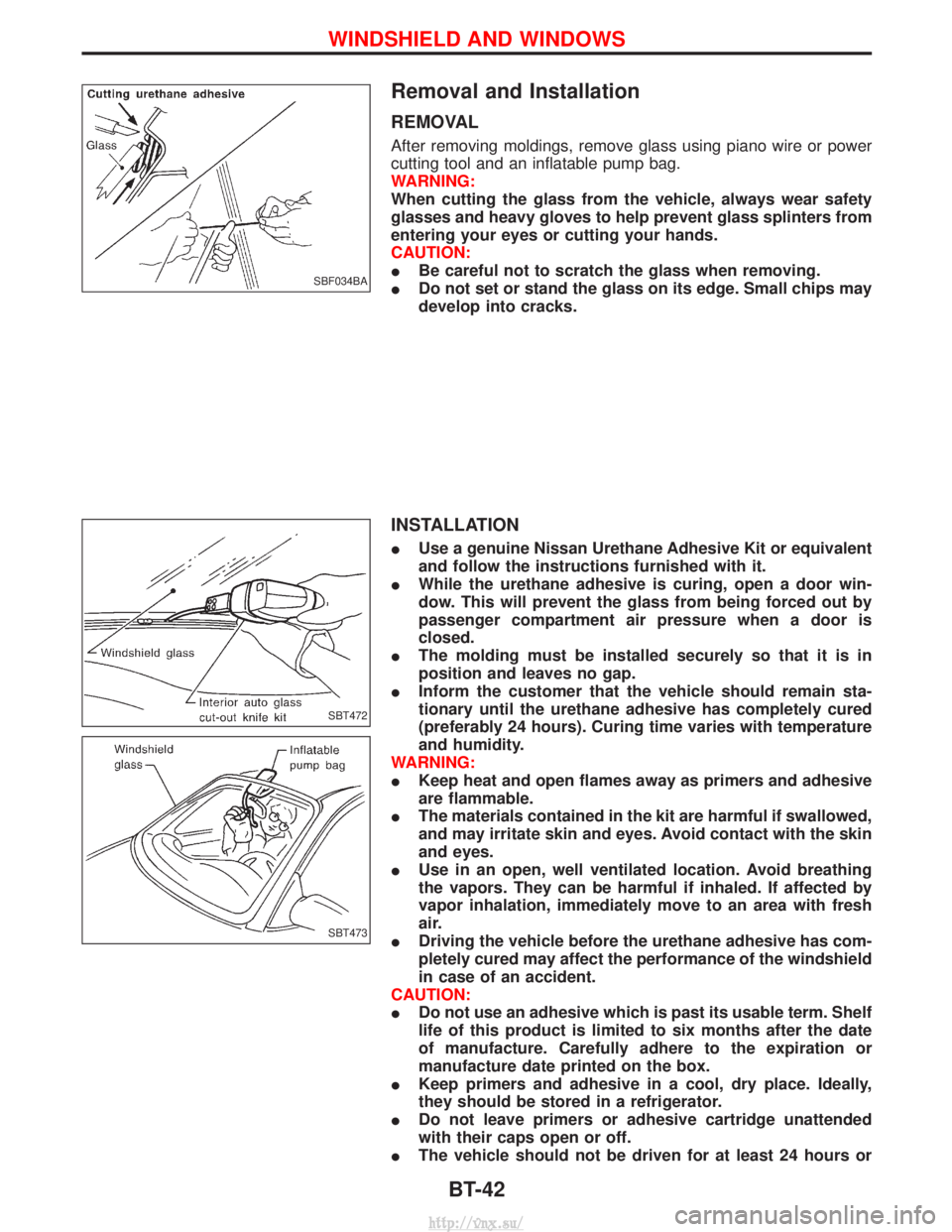
After removing moldings, remove glass using piano wire or power
cutting tool and an inflatable pump bag.
WARNING:
When cutting the glass from the vehicle, always wear safety
glasses and heavy gloves to help prevent glass splinters from
entering your eyes or cutting your hands.
CAUTION:
IBe careful not to scratch the glass when removing.
I Do not set or stand the glass on its edge. Small chips may
develop into cracks.
INSTALLATION
IUse a genuine Nissan Urethane Adhesive Kit or equivalent
and follow the instructions furnished with it.
I While the urethane adhesive is curing, open a door win-
dow. This will prevent the glass from being forced out by
passenger compartment air pressure when a door is
closed.
I The molding must be installed securely so that it is in
position and leaves no gap.
I Inform the customer that the vehicle should remain sta-
tionary until the urethane adhesive has completely cured
(preferably 24 hours). Curing time varies with temperature
and humidity.
WARNING:
I Keep heat and open flames away as primers and adhesive
are flammable.
I The materials contained in the kit are harmful if swallowed,
and may irritate skin and eyes. Avoid contact with the skin
and eyes.
I Use in an open, well ventilated location. Avoid breathing
the vapors. They can be harmful if inhaled. If affected by
vapor inhalation, immediately move to an area with fresh
air.
I Driving the vehicle before the urethane adhesive has com-
pletely cured may affect the performance of the windshield
in case of an accident.
CAUTION:
I Do not use an adhesive which is past its usable term. Shelf
life of this product is limited to six months after the date
of manufacture. Carefully adhere to the expiration or
manufacture date printed on the box.
I Keep primers and adhesive in a cool, dry place. Ideally,
they should be stored in a refrigerator.
I Do not leave primers or adhesive cartridge unattended
with their caps open or off.
I The vehicle should not be driven for at least 24 hours or
SBF034BA
SBT472
SBT473
WINDSHIELD AND WINDOWS
BT-42
http://vnx.su/
Page 1388 of 1833
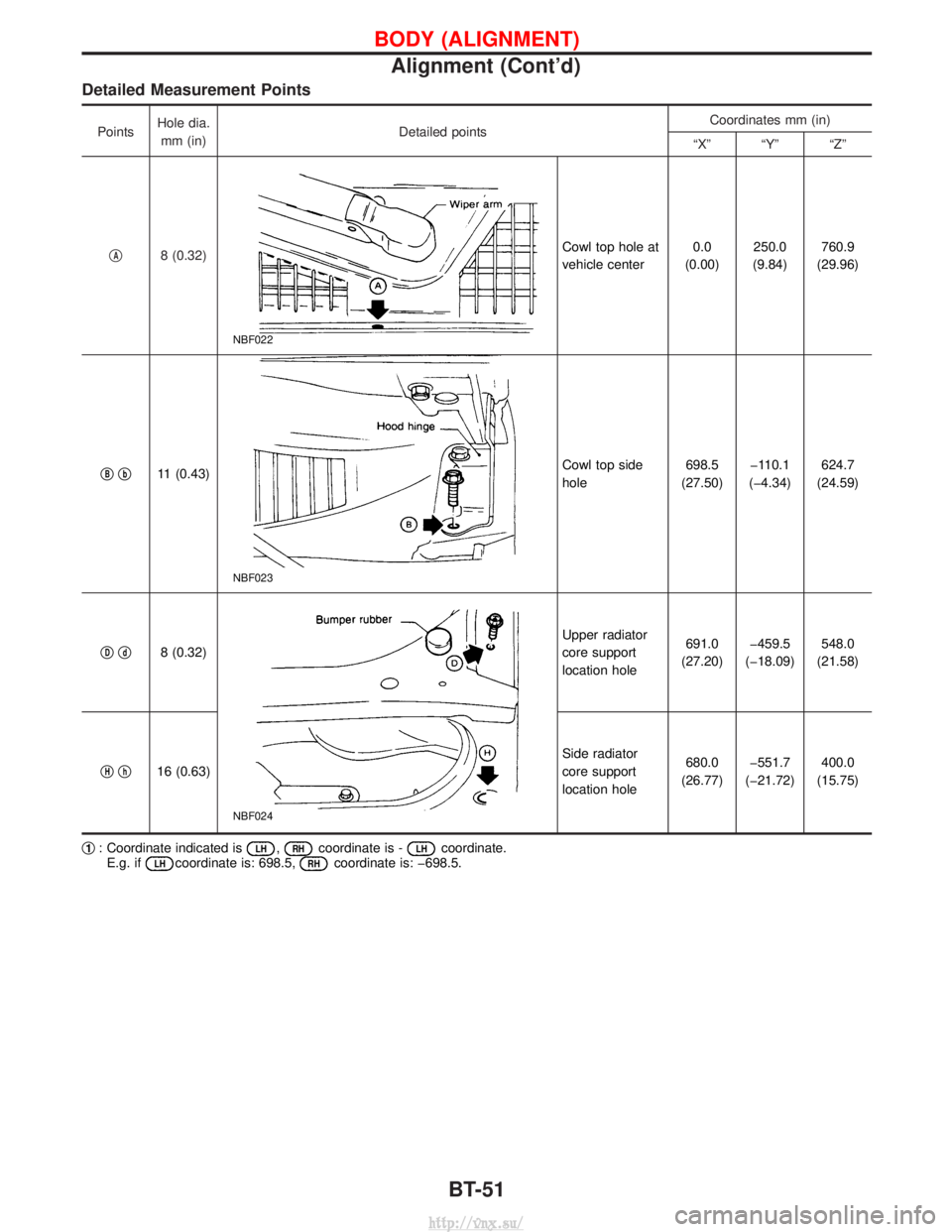
Detailed Measurement Points
PointsHole dia.
mm (in) Detailed points Coordinates mm (in)
ªXº ªYº ªZº
q
A8 (0.32)
NBF022
Cowl top hole at
vehicle center 0.0
(0.00) 250.0
(9.84) 760.9
(29.96)
q
Bqb11 (0.43)
NBF023
Cowl top side
hole 698.5
(27.50) þ110.1
(þ4.34) 624.7
(24.59)
q
Dqd8 (0.32)
NBF024
Upper radiator
core support
location hole 691.0
(27.20) þ459.5
(þ18.09) 548.0
(21.58)
q
Hqh16 (0.63) Side radiator
core support
location hole680.0
(26.77) þ551.7
(þ21.72) 400.0
(15.75)
q
1: Coordinate indicated isLH,RHcoordinate is -LHcoordinate.
E.g. ifLHcoordinate is: 698.5,RHcoordinate is: þ698.5.
BODY (ALIGNMENT)
Alignment (Cont'd)
BT-51
http://vnx.su/
Page 1389 of 1833
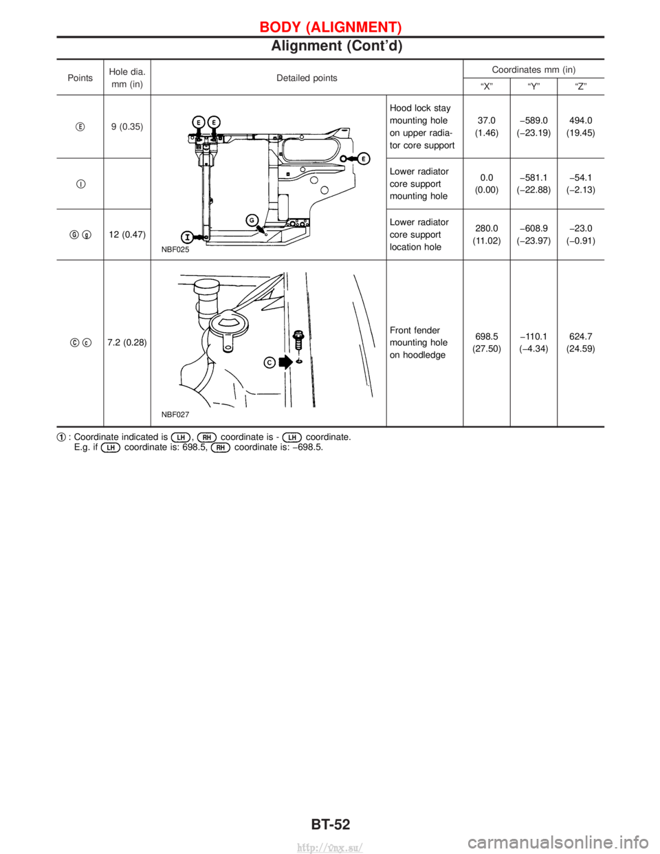
PointsHole dia.
mm (in) Detailed points Coordinates mm (in)
ªXº ªYº ªZº
q
E9 (0.35)
NBF025
Hood lock stay
mounting hole
on upper radia-
tor core support 37.0
(1.46) þ589.0
(þ23.19) 494.0
(19.45)
q
I
Lower radiator
core support
mounting hole 0.0
(0.00) þ581.1
(þ22.88) þ54.1
(þ2.13)
q
Gqg12 (0.47) Lower radiator
core support
location hole280.0
(11.02) þ608.9
(þ23.97) þ23.0
(þ0.91)
q
Cqc7.2 (0.28)
NBF027
Front fender
mounting hole
on hoodledge 698.5
(27.50) þ110.1
(þ4.34) 624.7
(24.59)
q
1: Coordinate indicated isLH,RHcoordinate is -LHcoordinate.
E.g. ifLHcoordinate is: 698.5,RHcoordinate is: þ698.5.
BODY (ALIGNMENT)
Alignment (Cont'd)
BT-52
http://vnx.su/
Page 1396 of 1833
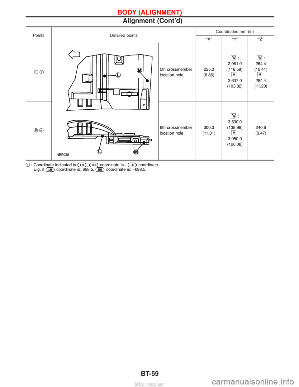
PointsDetailed points Coordinates mm (in)
ªXº ªYº ªZº
q
Lql
NBF038
5th crossmember
location hole 225.0
(8.86)
W:
2,961.0
(116.58)
H:
2,637.0
(103.82)
W:
264.4
(10.41)
H:
284.4
(11.20)
q
Mqm6th crossmember
location hole 300.0
(11.81)
W:
3,530.0
(138.98)
H:
3,050.0
(120.08) 240.6
(9.47)
q
1: Coordinate indicated isLH,RHcoordinate is -LHcoordinate.
E.g. ifLHcoordinate is: 698.5,RHcoordinate is: þ698.5.
BODY (ALIGNMENT)
Alignment (Cont'd)
BT-59
http://vnx.su/
Page 1428 of 1833
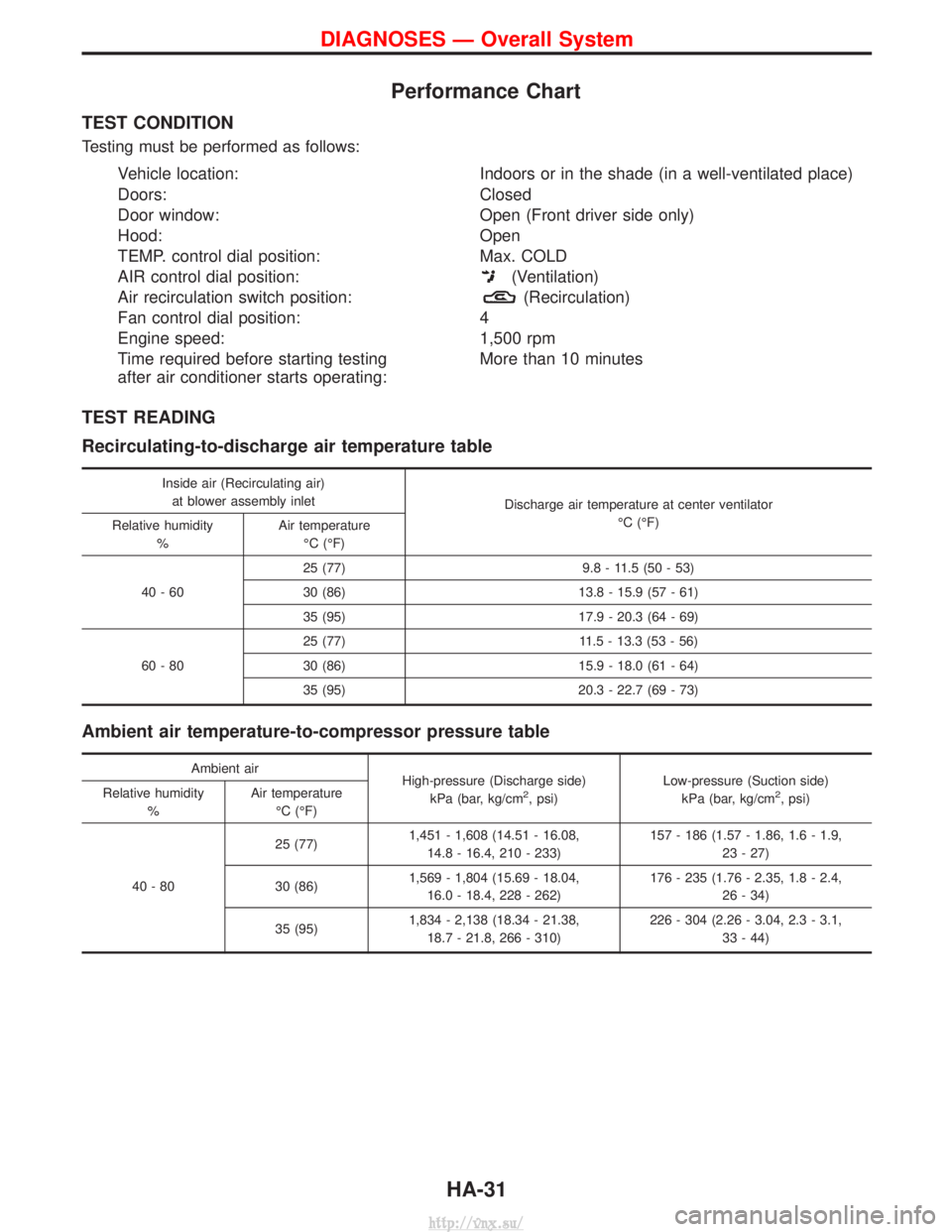
Performance Chart
TEST CONDITION
Testing must be performed as follows:
Vehicle location:Indoors or in the shade (in a well-ventilated place)
Doors: Closed
Door window: Open (Front driver side only)
Hood: Open
TEMP. control dial position: Max. COLD
AIR control dial position:
(Ventilation)
Air recirculation switch position:
(Recirculation)
Fan control dial position: 4
Engine speed: 1,500 rpm
Time required before starting testing
after air conditioner starts operating: More than 10 minutes
TEST READING
Recirculating-to-discharge air temperature table
Inside air (Recirculating air)
at blower assembly inlet Discharge air temperature at center ventilator
ÉC (ÉF)
Relative humidity
% Air temperature
ÉC (ÉF)
40-60 25 (77) 9.8 - 11.5 (50 - 53)
30 (86) 13.8 - 15.9 (57 - 61)
35 (95) 17.9 - 20.3 (64 - 69)
60-80 25 (77) 11.5 - 13.3 (53 - 56)
30 (86) 15.9 - 18.0 (61 - 64)
35 (95) 20.3 - 22.7 (69 - 73)
Ambient air temperature-to-compressor pressure table
Ambient air
High-pressure (Discharge side)
kPa (bar, kg/cm
2, psi) Low-pressure (Suction side)
kPa (bar, kg/cm2, psi)
Relative humidity
% Air temperature
ÉC (ÉF)
40-80 25 (77)
1,451 - 1,608 (14.51 - 16.08,
14.8 - 16.4, 210 - 233) 157 - 186 (1.57 - 1.86, 1.6 - 1.9,
23 - 27)
30 (86) 1,569 - 1,804 (15.69 - 18.04,
16.0 - 18.4, 228 - 262) 176 - 235 (1.76 - 2.35, 1.8 - 2.4,
26 - 34)
35 (95) 1,834 - 2,138 (18.34 - 21.38,
18.7 - 21.8, 266 - 310) 226 - 304 (2.26 - 3.04, 2.3 - 3.1,
33 - 44)
DIAGNOSES Ð Overall System
HA-31
http://vnx.su/
Page 1495 of 1833
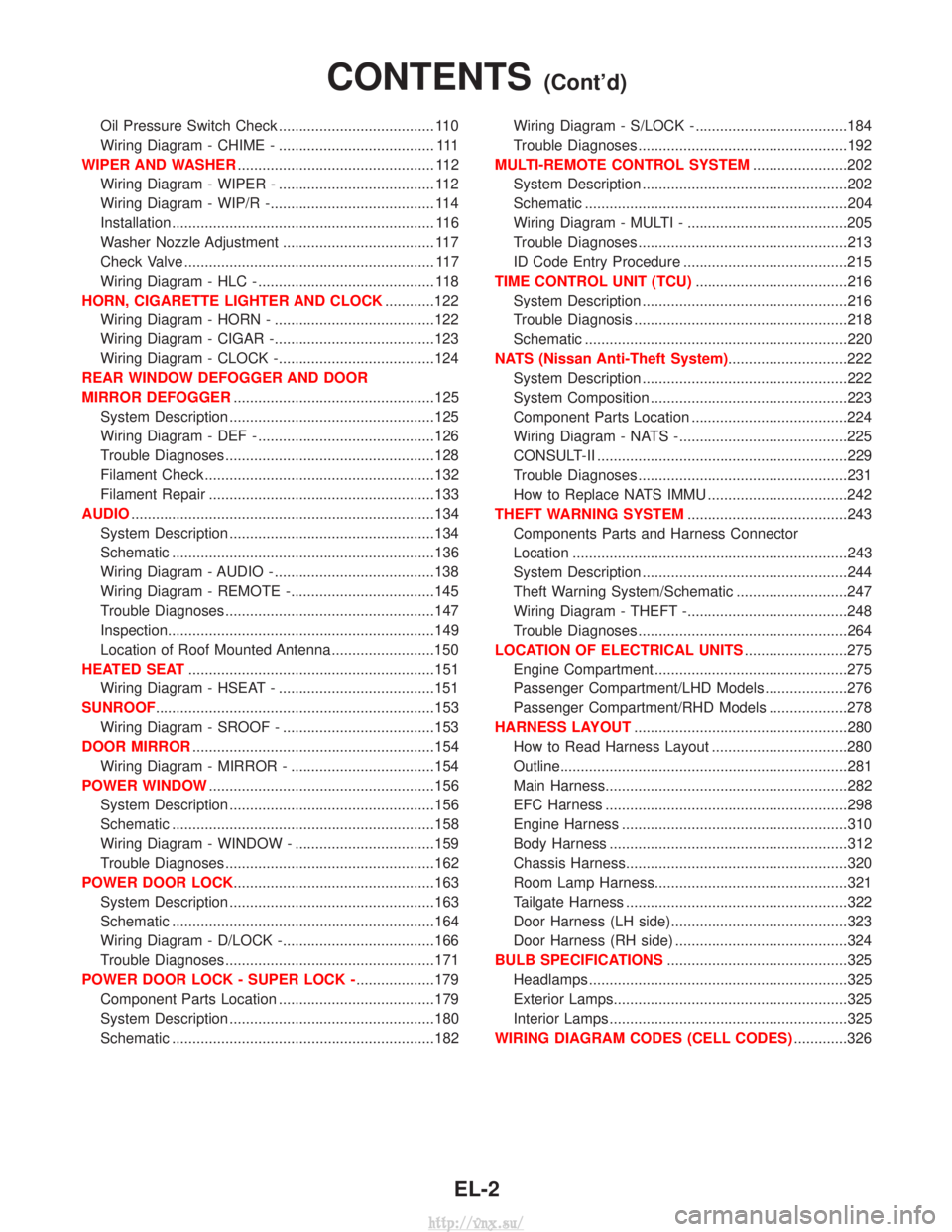
Oil Pressure Switch Check ...................................... 110
Wiring Diagram - CHIME - ...................................... 111
WIPER AND WASHER ................................................ 112
Wiring Diagram - WIPER - ...................................... 112
Wiring Diagram - WIP/R -........................................ 114
Installation ................................................................ 116
Washer Nozzle Adjustment ..................................... 117
Check Valve ............................................................. 117
Wiring Diagram - HLC - ........................................... 118
HORN, CIGARETTE LIGHTER AND CLOCK ............122
Wiring Diagram - HORN - .......................................122
Wiring Diagram - CIGAR -.......................................123
Wiring Diagram - CLOCK -......................................124
REAR WINDOW DEFOGGER AND DOOR
MIRROR DEFOGGER .................................................125
System Description ..................................................125
Wiring Diagram - DEF - ...........................................126
Trouble Diagnoses...................................................128
Filament Check ........................................................132
Filament Repair .......................................................133
AUDIO ........................................................................\
..134
System Description ..................................................134
Schematic ................................................................136
Wiring Diagram - AUDIO - .......................................138
Wiring Diagram - REMOTE -...................................145
Trouble Diagnoses...................................................147
Inspection.................................................................149
Location of Roof Mounted Antenna .........................150
HEATED SEAT ............................................................151
Wiring Diagram - HSEAT - ......................................151
SUNROOF ....................................................................153
Wiring Diagram - SROOF - .....................................153
DOOR MIRROR ...........................................................154
Wiring Diagram - MIRROR - ...................................154
POWER WINDOW .......................................................156
System Description ..................................................156
Schematic ................................................................158
Wiring Diagram - WINDOW - ..................................159
Trouble Diagnoses...................................................162
POWER DOOR LOCK .................................................163
System Description ..................................................163
Schematic ................................................................164
Wiring Diagram - D/LOCK -.....................................166
Trouble Diagnoses...................................................171
POWER DOOR LOCK - SUPER LOCK - ...................179
Component Parts Location ......................................179
System Description ..................................................180
Schematic ................................................................182 Wiring Diagram - S/LOCK - .....................................184
Trouble Diagnoses...................................................192
MULTI-REMOTE CONTROL SYSTEM .......................202
System Description ..................................................202
Schematic ................................................................204
Wiring Diagram - MULTI - .......................................205
Trouble Diagnoses...................................................213
ID Code Entry Procedure ........................................215
TIME CONTROL UNIT (TCU) .....................................216
System Description ..................................................216
Trouble Diagnosis ....................................................218
Schematic ................................................................220
NATS (Nissan Anti-Theft System) .............................222
System Description ..................................................222
System Composition ................................................223
Component Parts Location ......................................224
Wiring Diagram - NATS -.........................................225
CONSULT-II .............................................................229
Trouble Diagnoses...................................................231
How to Replace NATS IMMU ..................................242
THEFT WARNING SYSTEM .......................................243
Components Parts and Harness Connector
Location ...................................................................243
System Description ..................................................244
Theft Warning System/Schematic ...........................247
Wiring Diagram - THEFT -.......................................248
Trouble Diagnoses...................................................264
LOCATION OF ELECTRICAL UNITS .........................275
Engine Compartment ...............................................275
Passenger Compartment/LHD Models ....................276
Passenger Compartment/RHD Models ...................278
HARNESS LAYOUT ....................................................280
How to Read Harness Layout .................................280
Outline......................................................................281
Main Harness...........................................................282
EFC Harness ...........................................................298
Engine Harness .......................................................310
Body Harness ..........................................................312
Chassis Harness......................................................320
Room Lamp Harness...............................................321
Tailgate Harness ......................................................322
Door Harness (LH side)...........................................323
Door Harness (RH side) ..........................................324
BULB SPECIFICATIONS ............................................325
Headlamps ...............................................................325
Exterior Lamps.........................................................325
Interior Lamps ..........................................................325
WIRING DIAGRAM CODES (CELL CODES) .............326
CONTENTS(Cont'd)
EL-2
http://vnx.su/