2004 NISSAN TERRANO Location
[x] Cancel search: LocationPage 1011 of 1833
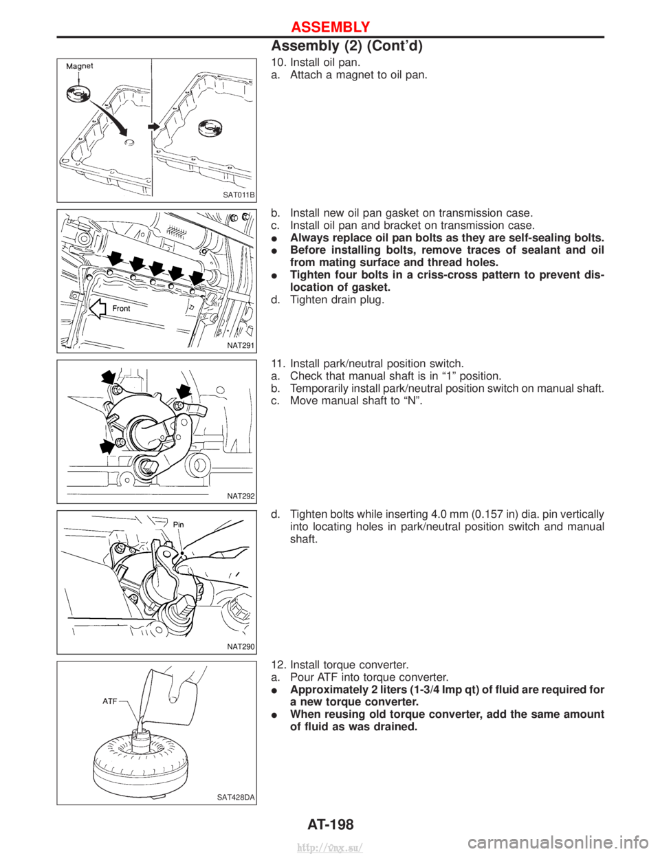
10. Install oil pan.
a. Attach a magnet to oil pan.
b. Install new oil pan gasket on transmission case.
c. Install oil pan and bracket on transmission case.
IAlways replace oil pan bolts as they are self-sealing bolts.
I Before installing bolts, remove traces of sealant and oil
from mating surface and thread holes.
I Tighten four bolts in a criss-cross pattern to prevent dis-
location of gasket.
d. Tighten drain plug.
11. Install park/neutral position switch.
a. Check that manual shaft is in ª1º position.
b. Temporarily install park/neutral position switch on manual shaft.
c. Move manual shaft to ªNº.
d. Tighten bolts while inserting 4.0 mm (0.157 in) dia. pin vertically into locating holes in park/neutral position switch and manual
shaft.
12. Install torque converter.
a. Pour ATF into torque converter.
I Approximately 2 liters (1-3/4 Imp qt) of fluid are required for
a new torque converter.
I When reusing old torque converter, add the same amount
of fluid as was drained.
SAT011B
NAT291
NAT292
NAT290
SAT428DA
ASSEMBLY
Assembly (2) (Cont'd)
AT-198
http://vnx.su/
Page 1168 of 1833
BRAKE SYSTEM
SECTION
BR
CONTENTS
PRECAUTIONS AND PREPARATION ............................3
Supplement Restraint System (SRS) ²AIR BAG²
and ²SEAT BELT PRE-TENSIONER² .........................3
Precautions ..................................................................3
Preparation ..................................................................4
CHECK AND ADJUSTMENT ..........................................5
Checking Brake Fluid Level.........................................5
Checking Brake Line ...................................................5
Changing Brake Fluid ..................................................5
Brake Burnishing Procedure........................................5
BRAKE HYDRAULIC LINE .............................................6
Bleeding Brake System ...............................................8
Removal .......................................................................9
Inspection.....................................................................9
Installation ....................................................................9
LOAD SENSING VALVE ...............................................10
Removal and Installation ...........................................10
Removal ..................................................................... 11
Installation .................................................................. 11
Inspection and Adjustment ........................................12
BRAKE PEDAL AND BRACKET ..................................14
Removal and Installation ...........................................14
Removal .....................................................................15
Installation ..................................................................15
Inspection...................................................................15
Adjustment .................................................................16
MASTER CYLINDER .....................................................17
Removal .....................................................................17
Installation ..................................................................17
BRAKE BOOSTER ........................................................18
Removal and Installation ...........................................18
Inspection...................................................................18
Installation ..................................................................19
VACUUM HOSE .............................................................20
Removal and Installation ...........................................20
Inspection...................................................................22
VACUUM PUMP (TD27Ti engine model) ....................24
Removal and Installation ...........................................24
Inspection...................................................................24 VACUUM PUMP (ZD30DDTi engine model)
...............26
Removal and Installation ...........................................26
FRONT DISC BRAKE ...................................................27
Pad Replacement ......................................................27
Removal .....................................................................28
Disassembly...............................................................28
Inspection...................................................................28
Assembly ...................................................................29
Inspection...................................................................29
Installation ..................................................................31
REAR DRUM BRAKE ...................................................32
Removal .....................................................................33
Shoe Replacement ....................................................34
Inspection...................................................................34
Installation ..................................................................34
PARKING BRAKE CONTROL ......................................36
Removal and Installation ...........................................36
Inspection...................................................................36
Adjustment .................................................................36
ANTI-LOCK BRAKE SYSTEM ......................................38
Purpose......................................................................38
Operation ...................................................................38
ABS Hydraulic Circuit ................................................38
System Description ....................................................39
Removal and Installation ...........................................43
TROUBLE DIAGNOSES ...............................................48
How to Perform Trouble Diagnoses for Quick
and Accurate Repair ..................................................48
Component Parts and Harness Connector
Location .....................................................................49
Circuit Diagram for Quick Pinpoint Check.................50
Wiring Diagram - ABS - .............................................51
CONSULT-II ...............................................................59
CONSULT-II Inspection Procedure............................60
Preliminary Check......................................................66
Ground Circuit Check ................................................67
Diagnostic Procedure 1 (Not self-diagnostic item) ....68
Diagnostic Procedure 2 (Warning lamp stays on
when ignition switch is turned ON)............................70
http://vnx.su/
Page 1192 of 1833
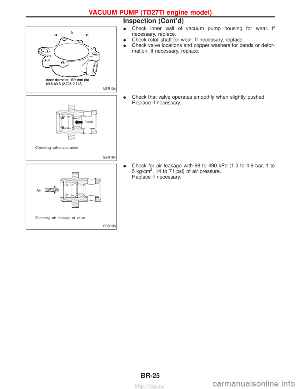
ICheck inner wall of vacuum pump housing for wear. If
necessary, replace.
I Check rotor shaft for wear. If necessary, replace.
I Check valve locations and copper washers for bends or defor-
mation. If necessary, replace.
I Check that valve operates smoothly when slightly pushed.
Replace if necessary.
I Check for air leakage with 98 to 490 kPa (1.0 to 4.9 bar, 1 to
5 kg/cm
2, 14 to 71 psi) of air pressure.
Replace if necessary.
NBR134
SBR194
SBR195
VACUUM PUMP (TD27Ti engine model)
Inspection (Cont'd)
BR-25
http://vnx.su/
Page 1212 of 1833
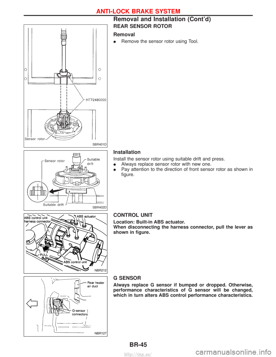
REAR SENSOR ROTOR
Removal
IRemove the sensor rotor using Tool.
Installation
Install the sensor rotor using suitable drift and press.
IAlways replace sensor rotor with new one.
I Pay attention to the direction of front sensor rotor as shown in
figure.
CONTROL UNIT
Location: Built-in ABS actuator.
When disconnecting the harness connector, pull the lever as
shown in figure.
G SENSOR
Always replace G sensor if bumped or dropped. Otherwise,
performance characteristics of G sensor will be changed,
which in turn alters ABS control performance characteristics.
SBR401D
SBR402D
NBR212
NBR127
ANTI-LOCK BRAKE SYSTEM
Removal and Installation (Cont'd)
BR-45
http://vnx.su/
Page 1216 of 1833
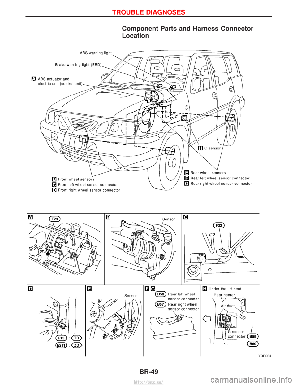
Component Parts and Harness Connector
Location
YBR264
TROUBLE DIAGNOSES
BR-49
http://vnx.su/
Page 1248 of 1833
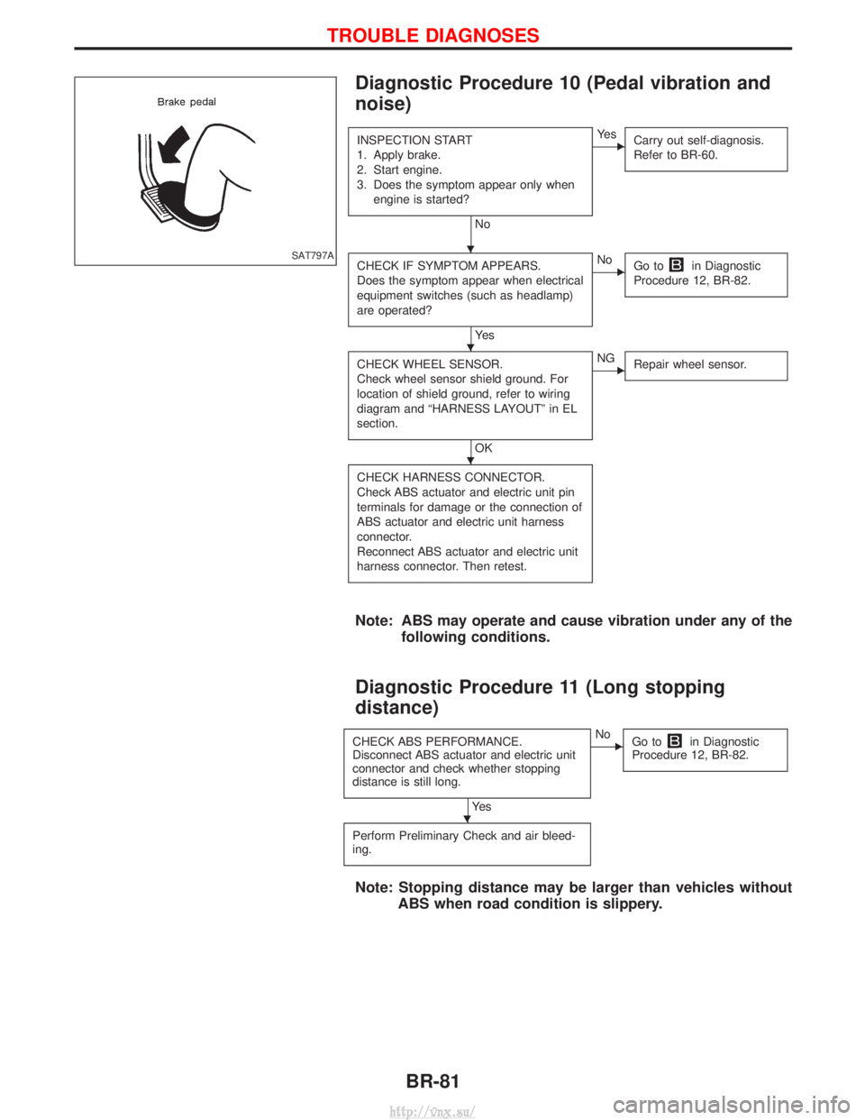
Diagnostic Procedure 10 (Pedal vibration and
noise)
INSPECTION START
1. Apply brake.
2. Start engine.
3. Does the symptom appear only whenengine is started?
No
EYe s Carry out self-diagnosis.
Refer to BR-60.
CHECK IF SYMPTOM APPEARS.
Does the symptom appear when electrical
equipment switches (such as headlamp)
are operated?
Ye s
ENoGo toin Diagnostic
Procedure 12, BR-82.
CHECK WHEEL SENSOR.
Check wheel sensor shield ground. For
location of shield ground, refer to wiring
diagram and ªHARNESS LAYOUTº in EL
section.
OK
ENG Repair wheel sensor.
CHECK HARNESS CONNECTOR.
Check ABS actuator and electric unit pin
terminals for damage or the connection of
ABS actuator and electric unit harness
connector.
Reconnect ABS actuator and electric unit
harness connector. Then retest.
Note: ABS may operate and cause vibration under any of the
following conditions.
Diagnostic Procedure 11 (Long stopping
distance)
CHECK ABS PERFORMANCE.
Disconnect ABS actuator and electric unit
connector and check whether stopping
distance is still long.
Ye s
ENoGo toin Diagnostic
Procedure 12, BR-82.
Perform Preliminary Check and air bleed-
ing.
Note: Stopping distance may be larger than vehicles without ABS when road condition is slippery.
SAT797AH
H
H
H
TROUBLE DIAGNOSES
BR-81
http://vnx.su/
Page 1274 of 1833
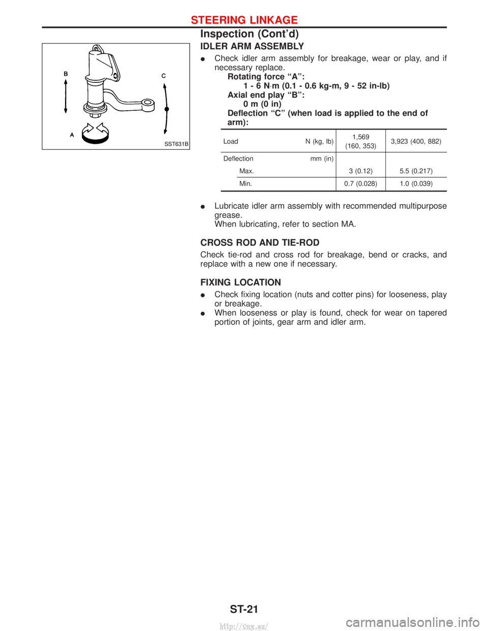
IDLER ARM ASSEMBLY
ICheck idler arm assembly for breakage, wear or play, and if
necessary replace.
Rotating force ªAº: 1-6N ×m (0.1 - 0.6 kg-m ,9-52in-lb)
Axial end play ªBº: 0m(0in)
Deflection ªCº (when load is applied to the end of
arm):
Load N (kg, lb)1,569
(160, 353) 3,923 (400, 882)
Deflection mm (in) Max. 3 (0.12) 5.5 (0.217)
Min. 0.7 (0.028) 1.0 (0.039)
ILubricate idler arm assembly with recommended multipurpose
grease.
When lubricating, refer to section MA.
CROSS ROD AND TIE-ROD
Check tie-rod and cross rod for breakage, bend or cracks, and
replace with a new one if necessary.
FIXING LOCATION
ICheck fixing location (nuts and cotter pins) for looseness, play
or breakage.
I When looseness or play is found, check for wear on tapered
portion of joints, gear arm and idler arm.
SST631B
STEERING LINKAGE
Inspection (Cont'd)
ST-21
http://vnx.su/
Page 1276 of 1833
RESTRAINT SYSTEM
SECTION
RS
CONTENTS
SEAT BELTS ...................................................................2
Precautions ..................................................................2
Front Seat Belt.............................................................4
Rear Seat Belt .............................................................6
SUPPLEMENTAL RESTRAINT SYSTEM (SRS) ............8
Precautions ..................................................................8
Preparation ..................................................................9
SRS Configuration .....................................................10
Seat Belt Pre-tensioner with Load Limiter................. 11
Built-in Type Side Air Bag.......................................... 11
SRS Component Parts Location ...............................12
Maintenance Items ....................................................12
Diagnosis Sensor Unit ...............................................13
Front Seat Belt Pre-tensioner ....................................14
Side Air Bag (Satellite) Sensor ..................................15
Driver Air Bag Module and Spiral Cable ...................16
Front Passenger Air Bag Module ..............................19 Front Side Air Bag Module ........................................20
Disposal of Air Bag Module and Seat Belt Pre-
tensioner ....................................................................22
Trouble Diagnoses Introduction.................................28
How to Perform Trouble Diagnoses for Quick
and Accurate Repair ..................................................31
Schematic ..................................................................33
Wiring Diagram - SRS -.............................................34
SRS Operation Check ...............................................38
Trouble Diagnoses with CONSULT-II..................39
Trouble Diagnoses without CONSULT-II.............48
Trouble Diagnoses: ²AIR BAG² Warning Lamp
Does Not Turn Off .....................................................56
Trouble Diagnoses: ²AIR BAG² Warning Lamp
Does Not Turn On .....................................................58
Collision Diagnosis ....................................................59
http://vnx.su/