2004 NISSAN TERRANO steering
[x] Cancel search: steeringPage 58 of 1833
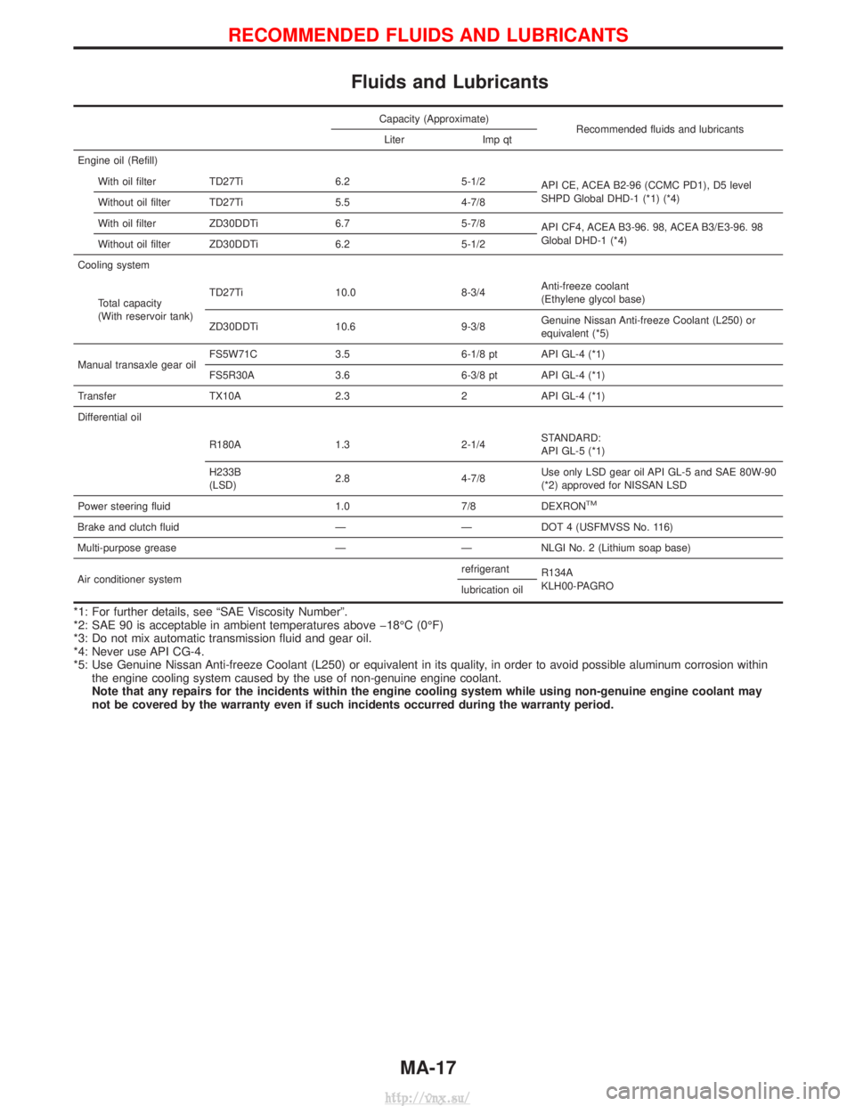
Fluids and Lubricants
Capacity (Approximate)Recommended fluids and lubricants
Liter Imp qt
Engine oil (Refill) With oil filter TD27Ti 6.2 5-1/2 API CE, ACEA B2-96 (CCMC PD1), D5 level
SHPD Global DHD-1 (*1) (*4)
Without oil filter TD27Ti 5.5 4-7/8
With oil filter ZD30DDTi 6.7 5-7/8 API CF4, ACEA B3-96. 98, ACEA B3/E3-96. 98
Global DHD-1 (*4)
Without oil filter ZD30DDTi 6.2 5-1/2
Cooling system
Total capacity
(With reservoir tank) TD27Ti 10.0 8-3/4
Anti-freeze coolant
(Ethylene glycol base)
ZD30DDTi 10.6 9-3/8 Genuine Nissan Anti-freeze Coolant (L250) or
equivalent (*5)
Manual transaxle gear oil FS5W71C 3.5 6-1/8 pt API GL-4 (*1)
FS5R30A 3.6 6-3/8 pt API GL-4 (*1)
Transfer TX10A 2.3 2 API GL-4 (*1)
Differential oil
R180A 1.3 2-1/4 STANDARD:
API GL-5 (*1)
H233B
(LSD) 2.8 4-7/8 Use only LSD gear oil API GL-5 and SAE 80W-90
(*2) approved for NISSAN LSD
Power steering fluid 1.0 7/8 DEXRON
TM
Brake and clutch fluid ÐÐDOT 4 (USFMVSS No. 116)
Multi-purpose grease Ð Ð NLGI No. 2 (Lithium soap base)
Air conditioner system refrigerant
R134A
KLH00-PAGRO
lubrication oil
*1: For further details, see ªSAE Viscosity Numberº.
*2: SAE 90 is acceptable in ambient temperatures above þ18ÉC (0ÉF)
*3: Do not mix automatic transmission fluid and gear oil.
*4: Never use API CG-4.
*5: Use Genuine Nissan Anti-freeze Coolant (L250) or equivalent in its quality, in order to avoid possible aluminum corrosion within
the engine cooling system caused by the use of non-genuine engine coolant.
Note that any repairs for the incidents within the engine cooling system while using non-genuine engine coolant may
not be covered by the warranty even if such incidents occurred during the warranty period.
RECOMMENDED FLUIDS AND LUBRICANTS
MA-17
http://vnx.su/
Page 61 of 1833
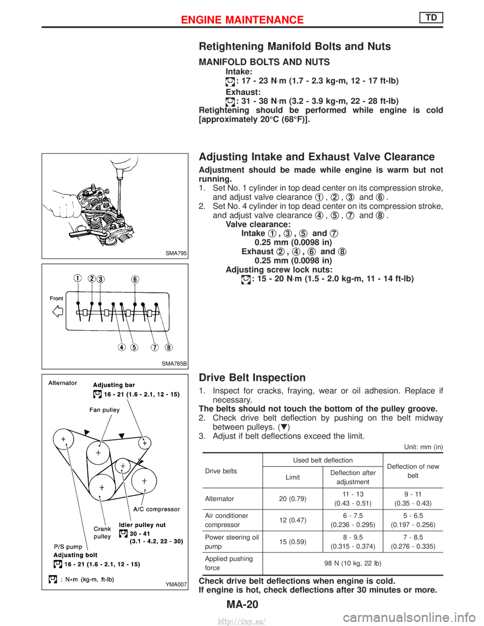
Retightening Manifold Bolts and Nuts
MANIFOLD BOLTS AND NUTS
Intake:
:17-23N×m (1.7 - 2.3 kg-m, 12 - 17 ft-lb)
Exhaust:
:31-38N ×m (3.2 - 3.9 kg-m, 22 - 28 ft-lb)
Retightening should be performed while engine is cold
[approximately 20ÉC (68ÉF)].
Adjusting Intake and Exhaust Valve Clearance
Adjustment should be made while engine is warm but not
running.
1. Set No. 1 cylinder in top dead center on its compression stroke, and adjust valve clearance q
1,q2,q3and q6.
2. Set No. 4 cylinder in top dead center on its compression stroke, and adjust valve clearance q
4,q5,q7and q8.
Valve clearance: Intake q
1,q3,q5and q7
0.25 mm (0.0098 in)
Exhaust q
2,q4,q6and q8
0.25 mm (0.0098 in)
Adjusting screw lock nuts:
:15-20N ×m (1.5 - 2.0 kg-m, 11 - 14 ft-lb)
Drive Belt Inspection
1. Inspect for cracks, fraying, wear or oil adhesion. Replace if
necessary.
The belts should not touch the bottom of the pulley groove.
2. Check drive belt deflection by pushing on the belt midway between pulleys. (H)
3. Adjust if belt deflections exceed the limit.
Unit: mm (in)
Drive belts Used belt deflection
Deflection of new
belt
Limit Deflection after
adjustment
Alternator 20 (0.79) 11-13
(0.43 - 0.51) 9-11
(0.35 - 0.43)
Air conditioner
compressor 12 (0.47)6 - 7.5
(0.236 - 0.295) 5 - 6.5
(0.197 - 0.256)
Power steering oil
pump 15 (0.59)8 - 9.5
(0.315 - 0.374) 7 - 8.5
(0.276 - 0.335)
Applied pushing
force 98 N (10 kg, 22 lb)
Check drive belt deflections when engine is cold.
If engine is hot, check deflections after 30 minutes or more.
SMA795
SMA785B
YMA007
ENGINE MAINTENANCETD
MA-20
http://vnx.su/
Page 84 of 1833

Changing Brake Fluid
1. Drain brake fluid from each air bleeder valve.
2. Refill until new brake fluid comes out from each air bleedervalve. Use same procedure as in bleeding hydraulic system to
refill brake fluid.
Refer to section BR.
I Refill with recommended brake fluid ªDOT 4º.
I Never reuse drained brake fluid.
I Be careful not to splash brake fluid on painted areas.
Balancing Wheels
Adjust wheel balance using the road wheel center.
Radial runout limit:Steel wheel:0.5 mm (0.020 in)
Aluminum wheel: 0.3 mm (0.012 in)
Lateral runout limit: Steel wheel:0.8 mm (0.031 in)
Aluminum wheel: 0.3 mm (0.012 in)
Tire Rotation
Wheel nuts
: 118 - 147 N ×m (12 - 15 kg-m, 87 - 108 ft-lb)
Checking Steering Gear and Linkage
STEERING GEAR
ICheck gear housing and boots for looseness, damage or
grease leakage.
I Check connection with steering column for looseness.
STEERING LINKAGE
ICheck ball joint, dust cover and other component parts for
looseness, wear damage or grease leakage.
SBR992
EMA039
EMA051
CHASSIS AND BODY MAINTENANCE
MA-43
http://vnx.su/
Page 85 of 1833
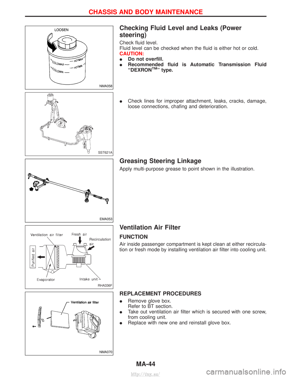
Checking Fluid Level and Leaks (Power
steering)
Check fluid level.
Fluid level can be checked when the fluid is either hot or cold.
CAUTION:
IDo not overfill.
I Recommended fluid is Automatic Transmission Fluid
ªDEXRON
TMº type.
I Check lines for improper attachment, leaks, cracks, damage,
loose connections, chafing and deterioration.
Greasing Steering Linkage
Apply multi-purpose grease to point shown in the illustration.
Ventilation Air Filter
FUNCTION
Air inside passenger compartment is kept clean at either recircula-
tion or fresh mode by installing ventilation air filter into cooling unit.
REPLACEMENT PROCEDURES
IRemove glove box.
Refer to BT section.
I Take out ventilation air filter which is secured with one screw,
from cooling unit.
I Replace with new one and reinstall glove box.
NMA058
SST621A
EMA053
RHA336F
NMA070
CHASSIS AND BODY MAINTENANCE
MA-44
http://vnx.su/
Page 89 of 1833
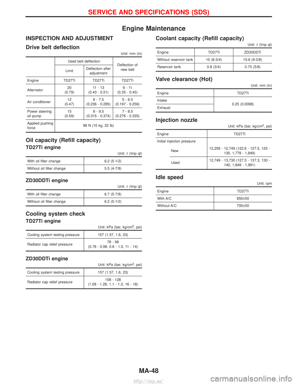
Engine Maintenance
INSPECTION AND ADJUSTMENT
Drive belt deflection
Unit: mm (in)
Used belt deflectionDeflection of
new belt
Limit Deflection after
adjustment
Engine TD27Ti TD27Ti TD27Ti
Alternator 20
(0.79) 11-13
(0.43 - 0.51) 9-11
(0.35 - 0.43)
Air conditioner 12
(0.47) 6 - 7.5
(0.236 - 0.295) 5 - 6.5
(0.197 - 0.256)
Power steering
oil pump 15
(0.59) 8 - 9.5
(0.315 - 0.374) 7 - 8.5
(0.276 - 0.335)
Applied pushing
force 98 N (10 kg, 22 lb)
Oil capacity (Refill capacity)
TD27Ti engine
Unit:
(Imp qt)
With oil filter change 6.2 (5-1/2)
Without oil filter change 5.5 (4-7/8)
ZD30DDTi engine
Unit: (Imp qt)
With oil filter change 6.7 (5-7/8)
Without oil filter change 6.2 (5-1/2)
Cooling system check
TD27Ti engine
Unit: kPa (bar, kg/cm2, psi)
Cooling system testing pressure 157 (1.57, 1.6, 23)
Radiator cap relief pressure 78-98
(0.78 - 0.98, 0.8 - 1.0, 11 - 14)
ZD30DDTi engine
Unit: kPa (bar, kg/cm2, psi)
Cooling system testing pressure 157 (1.57, 1.6, 23)
Radiator cap relief pressure 108 - 128
(1.08 - 1.28, 1.1 - 1.3, 16 - 18)
Coolant capacity (Refill capacity)
Unit: (Imp qt)
Engine TD27TiZD30DDTi
Without reservoir tank 10 (8-3/4) 10.6 (9-3/8)
Reservoir tank 0.8 (3/4) 0.75 (5/8)
Valve clearance (Hot)
Unit: mm (in)
Engine TD27Ti
Intake 0.25 (0.0098)
Exhaust
Injection nozzle
Unit: kPa (bar, kg/cm2, psi)
Engine TD27Ti
Initial injection pressure
New 12,259 - 12,749 (122.6 - 127.5, 125 -
130, 1,778 - 1,849)
Used 12,749 - 13,730 (127.5 - 137.3, 130 -
140, 1,849 - 1,991)
Idle speed
Unit: rpm
Engine TD27Ti
With A/C 850 50
Without A/C 700 50
SERVICE AND SPECIFICATIONS (SDS)
MA-48
http://vnx.su/
Page 90 of 1833
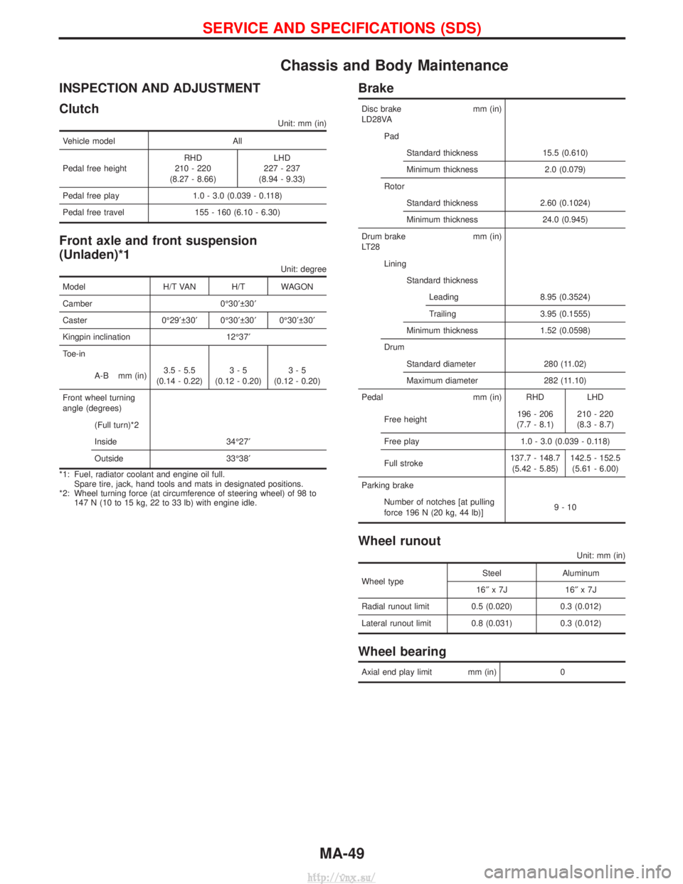
Chassis and Body Maintenance
INSPECTION AND ADJUSTMENT
Clutch
Unit: mm (in)
Vehicle modelAll
Pedal free height RHD
210 - 220
(8.27 - 8.66) LHD
227 - 237
(8.94 - 9.33)
Pedal free play 1.0 - 3.0 (0.039 - 0.118)
Pedal free travel 155 - 160 (6.10 - 6.30)
Front axle and front suspension
(Unladen)*1
Unit: degree
Model H/T VAN H/T WAGON
Camber 0É30¢ 30¢
Caster 0É29¢ 30¢ 0É30¢ 30¢ 0É30¢ 30¢
Kingpin inclination 12É37¢
Toe-in
A-B mm (in) 3.5 - 5.5
(0.14 - 0.22) 3-5
(0.12 - 0.20) 3-5
(0.12 - 0.20)
Front wheel turning
angle (degrees) (Full turn)*2
Inside 34É27¢
Outside 33É38¢
*1: Fuel, radiator coolant and engine oil full. Spare tire, jack, hand tools and mats in designated positions.
*2: Wheel turning force (at circumference of steering wheel) of 98 to 147 N (10 to 15 kg, 22 to 33 lb) with engine idle.
Brake
Disc brake mm (in)
LD28VA
PadStandard thickness 15.5 (0.610)
Minimum thickness 2.0 (0.079)
Rotor Standard thickness 2.60 (0.1024)
Minimum thickness 24.0 (0.945)
Drum brake mm (in)
LT28 LiningStandard thicknessLeading 8.95 (0.3524)
Trailing 3.95 (0.1555)
Minimum thickness 1.52 (0.0598)
Drum Standard diameter 280 (11.02)
Maximum diameter 282 (11.10)
Pedal mm (in) RHD LHD
Free height 196 - 206
(7.7 - 8.1) 210 - 220
(8.3 - 8.7)
Free play 1.0 - 3.0 (0.039 - 0.118)
Full stroke 137.7 - 148.7
(5.42 - 5.85) 142.5 - 152.5
(5.61 - 6.00)
Parking brake Number of notches [at pulling
force 196 N (20 kg, 44 lb)] 9-10
Wheel runout
Unit: mm (in)
Wheel typeSteel Aluminum
16² x7J 16 ²x7J
Radial runout limit 0.5 (0.020) 0.3 (0.012)
Lateral runout limit 0.8 (0.031) 0.3 (0.012)
Wheel bearing
Axial end play limit mm (in) 0
SERVICE AND SPECIFICATIONS (SDS)
MA-49
http://vnx.su/
Page 118 of 1833
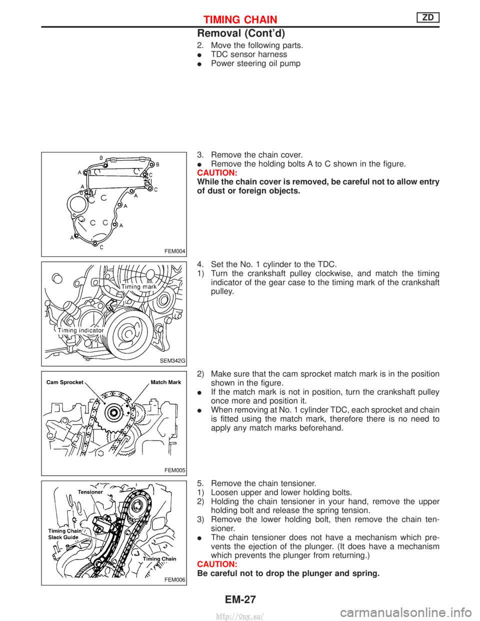
2. Move the following parts.
ITDC sensor harness
I Power steering oil pump
3. Remove the chain cover.
I Remove the holding bolts A to C shown in the figure.
CAUTION:
While the chain cover is removed, be careful not to allow entry
of dust or foreign objects.
4. Set the No. 1 cylinder to the TDC.
1) Turn the crankshaft pulley clockwise, and match the timing indicator of the gear case to the timing mark of the crankshaft
pulley.
2) Make sure that the cam sprocket match mark is in the position shown in the figure.
I If the match mark is not in position, turn the crankshaft pulley
once more and position it.
I When removing at No. 1 cylinder TDC, each sprocket and chain
is fitted using the match mark, therefore there is no need to
apply any match marks beforehand.
5. Remove the chain tensioner.
1) Loosen upper and lower holding bolts.
2) Holding the chain tensioner in your hand, remove the upper holding bolt and release the spring tension.
3) Remove the lower holding bolt, then remove the chain ten- sioner.
I The chain tensioner does not have a mechanism which pre-
vents the ejection of the plunger. (It does have a mechanism
which prevents the plunger from returning.)
CAUTION:
Be careful not to drop the plunger and spring.
FEM004
SEM342G
FEM005
FEM006
TIMING CHAINZD
Removal (Cont'd)
EM-27
http://vnx.su/
Page 155 of 1833

Engine room (Left)
3. Remove air duct and air cleaner case.
4. Disconnect vacuum hose to the vehicle on the engine.
5. Disconnect harness connectors from alternator and air com-pressor.
6. Remove alternator.
7. After removing refrigerant, remove pipes of air compressor and inlet/outlet.
8. Disconnect heating hose, install blank cap to hose to prevent coolant from leaking.
9. Remove heating pipe.
10. Remove heat insulator.
11. Remove catalytic converter.
Engine room (Right)
12. Remove power steering reservoir tank from bracket, and fix it to the vehicle with a rope.
CAUTION:
Keep the reservoir tank level when fixing to prevent oil leak.
13. Remove fuel feed and return hoses.
CAUTION:
Install blank caps immediately to avoid fuel leakage.
14. Remove all harness connectors on the engine, and move har- nesses to the side of the vehicle.
Vehicle underfloor
15. Remove starter motor.
16. Detach A/T oil cooler pipes from oil pan. (A/T model)
17. Remove rear propeller shaft.
18. Remove mounting bolts to secure the engine to transmission.
1) Remove torque converter installation bolt. (A/T model)
2) Lift transmission bottom with transmission jack, and removerear mount members from the vehicle.
3) Lower transmission with the jack, and remove upper mounting bolts securing the engine to transmission.
4) Lift transmission with the jack, and reinstall rear mount mem- bers to the vehicle.
5) Position the jack to the front side of transmission.
6) Remove remaining mounting bolts securing the engine to trans- mission.
Removal operation
19. Remove air conditioner high pressure pipes at the rear of theengine room.
I This is due to some inconvenience in the rear slinger installa-
tion.
20. Install the engine slingers (standard service part) to front-left and rear-right.
:25-28N ×m (2.5 - 2.9 kg-m, 18 - 20 ft-lb)
WARNING:
For engines without engine slingers, attach proper slingers
and bolts described in the PARTS CATALOG.
FEM082
ENGINE REMOVALZD
Removal (Cont'd)
EM-64
http://vnx.su/