2004 NISSAN TERRANO steering
[x] Cancel search: steeringPage 303 of 1833
REMOVAL
1. Remove the following:
IEngine coolant draining
I Charge air cooler
I Air inlet pipe
I Throttle body
I Rocker cover
I Oil level gauge guide
I EGR cooler
I EGR guide tube
I EGR volume control solenoid valve
I Fuel hose
I Injection tube
I Radiator upper hose
I Radiator shroud
I Cooling fan
I Drive belt
I Vacuum pipe
I Vacuum pump
2. Move the power steering pump.
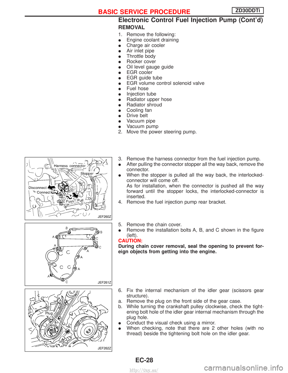
3. Remove the harness connector from the fuel injection pump.
I After pulling the connector stopper all the way back, remove the
connector.
I When the stopper is pulled all the way back, the interlocked-
connector will come off.
As for installation, when the connector is pushed all the way
forward until the stopper locks, the interlocked-connector is
inserted.
4. Remove the fuel injection pump rear bracket.
5. Remove the chain cover.
I Remove the installation bolts A, B, and C shown in the figure
(left).
CAUTION:
During chain cover removal, seal the opening to prevent for-
eign objects from getting into the engine.
6. Fix the internal mechanism of the idler gear (scissors gear structure).
a. Remove the plug on the front side of the gear case.
b. While turning the crankshaft pulley clockwise, check the tight- ening bolt hole of the idler gear internal mechanism through the
plug hole.
I Conduct the visual check using a mirror.
I When checking, note that there are 2 other holes (with no
thread) beside the tightening bolt hole on the idler gear.
JEF260Z
JEF261Z
JEF262Z
BASIC SERVICE PROCEDUREZD30DDTi
Electronic Control Fuel Injection Pump (Cont'd)
EC-28
http://vnx.su/
Page 325 of 1833
Basic Inspection
Precaution:
Perform Basic Inspection without electrical or mechanical
loads applied;
IShift lever is in neutral position,
I Heat up switch is OFF,
I Headlamp switch is OFF,
I Air conditioner switch is OFF,
I Rear defogger switch is OFF,
I Steering wheel is in the straight-ahead position, etc.
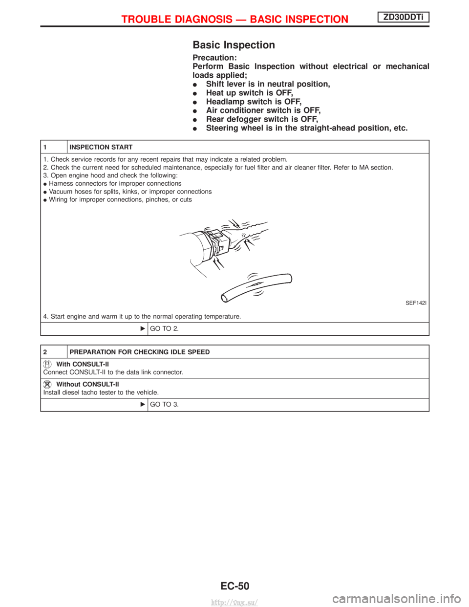
1 INSPECTION START
1. Check service records for any recent repairs that may indicate a related problem.
2. Check the current need for scheduled maintenance, especially for fuel filter and air cleaner filter. Refer to MA section.
3. Open engine hood and check the following:
IHarness connectors for improper connections
I Vacuum hoses for splits, kinks, or improper connections
I Wiring for improper connections, pinches, or cuts
SEF142I
4. Start engine and warm it up to the normal operating temperature.
EGO TO 2.
2 PREPARATION FOR CHECKING IDLE SPEED
With CONSULT-II
Connect CONSULT-II to the data link connector.
Without CONSULT-II
Install diesel tacho tester to the vehicle.
EGO TO 3.
TROUBLE DIAGNOSIS Ð BASIC INSPECTIONZD30DDTi
EC-50
http://vnx.su/
Page 636 of 1833
Basic Inspection
Precaution:
Perform Basic Inspection without electrical or mechanical
loads applied;
IHeadlamp switch is OFF,
I Air conditioner switch is OFF,
I Rear defogger switch is OFF,
I Steering wheel is in the straight-ahead position, etc.
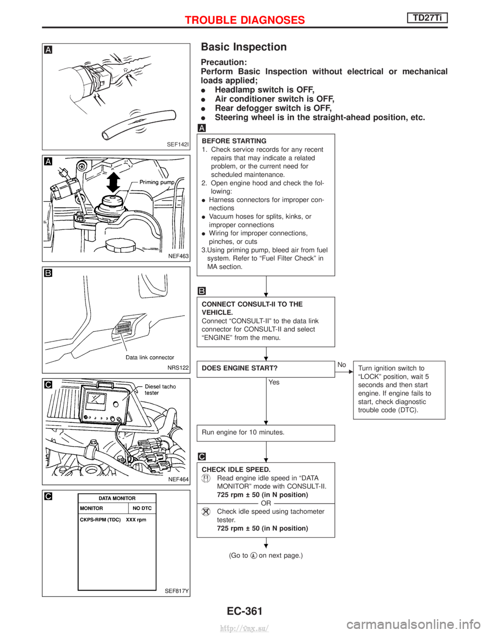
BEFORE STARTING
1. Check service records for any recent
repairs that may indicate a related
problem, or the current need for
scheduled maintenance.
2. Open engine hood and check the fol- lowing:
I Harness connectors for improper con-
nections
I Vacuum hoses for splits, kinks, or
improper connections
I Wiring for improper connections,
pinches, or cuts
3.Using priming pump, bleed air from fuel system. Refer to ªFuel Filter Checkº in
MA section.
CONNECT CONSULT-II TO THE
VEHICLE.
Connect ªCONSULT-IIº to the data link
connector for CONSULT-II and select
ªENGINEº from the menu.
DOES ENGINE START?
Ye s
ENo Turn ignition switch to
ªLOCKº position, wait 5
seconds and then start
engine. If engine fails to
start, check diagnostic
trouble code (DTC).
Run engine for 10 minutes.
CHECK IDLE SPEED.
Read engine idle speed in ªDATA
MONITORº mode with CONSULT-II.
725 rpm 50 (in N position)
----------------------------------------------------------------------------------------------------------------------------------- -OR------------------------------------------------------------------------------------------------------------------------------------
Check idle speed using tachometer
tester.
725 rpm 50 (in N position)
(Go to qAon next page.)
SEF142I
NEF463
NRS122
NEF464
SEF817Y
H
H
H
H
H
TROUBLE DIAGNOSESTD27Ti
EC-361
http://vnx.su/
Page 817 of 1833
Supplemental Restraint System (SRS) ªAIR
BAGº and ªSEAT BELT PRE-TENSIONERº
The Supplemental Restraint System such as ªAIR BAGº and ªSEAT BELT PRE-TENSIONERº used along with
a seat belt, helps to reduce the risk or severity of injury to the driver and front passenger for certain types of
collision. The SRS composition which is available to NISSAN MODEL R20 is as follows (The composition
varies according to the destination and optional equipment.):
IFor a frontal collision
The Supplemental Restraint System consists of driver air bag module (located in the center of the steer-
ing wheel), front passenger air bag module (located on the instrument panel on passenger side), front seat
belt pre-tensioners, a diagnosis sensor unit, warning lamp, wiring harness and spiral cable.
I For a side collision
The Supplemental Restraint System consists of front side air bag module (located in the outer side of front
seat), side air bag (satellite) sensor, diagnosis sensor unit (one of components of air bags for a frontal
collision), wiring harness, warning lamp (one of components of air bags for a frontal collision).
WARNING:
I To avoid rendering the SRS inoperative, which could increase the risk of personal injury or death
in the event of a collision which would result in air bag inflation, all maintenance should be per-
formed by an authorized NISSAN dealer.
I Improper maintenance, including incorrect removal and installation of the SRS, can lead to per-
sonal injury caused by unintentional activation of the system.
I Do not use electrical test equipment on any circuit related to the SRS unless instructed to in this
Service Manual. Spiral cable and wiring harnesses covered with yellow insulation tape either just
before the harness connectors or for the complete harness are related to the SRS.
Precautions for SRS ªAIR BAGº and ªSEAT
BELT PRE-TENSIONERº Service
IDo not use electrical test equipment to check SRS circuits unless instructed to in this Service Manual.
I Before servicing the SRS, turn ignition switch ªOFFº, disconnect both battery cables and wait at least 3
minutes.
For approximately 3 minutes after the cables are removed, it is still possible for the air bag and seat belt
pre-tensioner to deploy. Therefore, do not work on any SRS connectors or wires until at least 3 minutes
have passed.
I Diagnosis sensor unit must always be installed with their arrow marks ª +º pointing towards the front of
the vehicle for proper operation. Also check diagnosis sensor unit for cracks, deformities or rust before
installation and replace as required.
I The spiral cable must be aligned with the neutral position since its rotations are limited. Do not attempt to
turn steering wheel or column after removal of steering gear.
I Handle air bag module carefully. Always place driver and front passenger air bag modules with the pad
side facing upward and place front side air bag module (built-in type) standing with stud bolt side setting
bottom.
I Conduct self-diagnosis to check entire SRS for proper function after replacing any components.
I After air bag inflates, the front instrument panel assembly should be replaced if damaged.
Precautions
IBefore proceeding with disassembly, thoroughly clean the outside of the transmission. It is important to
prevent the internal parts from becoming contaminated by dirt or other foreign matter.
I Disassembly should be done in a clean work area.
I Use lint-free cloth or towels for wiping parts clean. Common shop rags can leave fibers that could inter-
fere with the operation of the transmission.
I Place disassembled parts in order for easier and proper assembly.
I All parts should be carefully cleaned with a general purpose, non-flammable solvent before inspection or
reassembly.
I Gaskets, seals and O-rings should be replaced any time the transmission is disassembled.
I It is very important to perform functional tests whenever they are indicated.
I The valve body contains precision parts and requires extreme care when parts are removed and serviced.
Place removed parts in a parts rack in order to replace them in correct positions and sequences. Care will
also prevent springs and small parts from becoming scattered or lost.
I Properly installed valves, sleeves, plugs, etc. will slide along bores in valve body under their own weight.
PREPARATION AND PRECAUTIONS
AT- 4
http://vnx.su/
Page 1119 of 1833
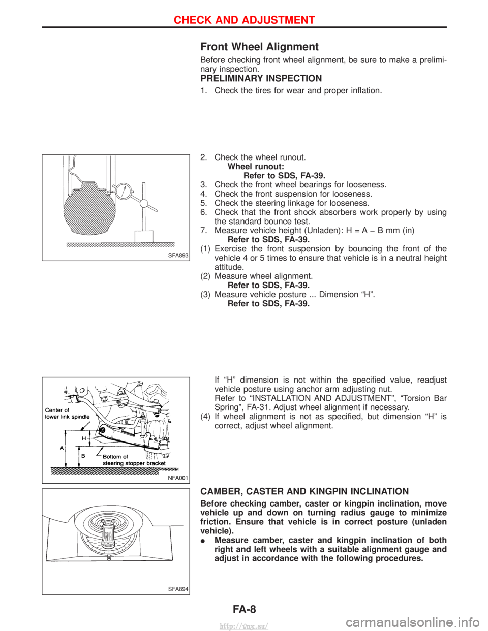
Front Wheel Alignment
Before checking front wheel alignment, be sure to make a prelimi-
nary inspection.
PRELIMINARY INSPECTION
1. Check the tires for wear and proper inflation.
2. Check the wheel runout.Wheel runout:Refer to SDS, FA-39.
3. Check the front wheel bearings for looseness.
4. Check the front suspension for looseness.
5. Check the steering linkage for looseness.
6. Check that the front shock absorbers work properly by using the standard bounce test.
7. Measure vehicle height (Unladen): H = A þ B mm (in) Refer to SDS, FA-39.
(1) Exercise the front suspension by bouncing the front of the vehicle 4 or 5 times to ensure that vehicle is in a neutral height
attitude.
(2) Measure wheel alignment. Refer to SDS, FA-39.
(3) Measure vehicle posture ... Dimension ªHº. Refer to SDS, FA-39.
If ªHº dimension is not within the specified value, readjust
vehicle posture using anchor arm adjusting nut.
Refer to ªINSTALLATION AND ADJUSTMENTº, ªTorsion Bar
Springº, FA-31. Adjust wheel alignment if necessary.
(4) If wheel alignment is not as specified, but dimension ªHº is correct, adjust wheel alignment.
CAMBER, CASTER AND KINGPIN INCLINATION
Before checking camber, caster or kingpin inclination, move
vehicle up and down on turning radius gauge to minimize
friction. Ensure that vehicle is in correct posture (unladen
vehicle).
IMeasure camber, caster and kingpin inclination of both
right and left wheels with a suitable alignment gauge and
adjust in accordance with the following procedures.
SFA893
NFA001
SFA894
CHECK AND ADJUSTMENT
FA-8
http://vnx.su/
Page 1122 of 1833
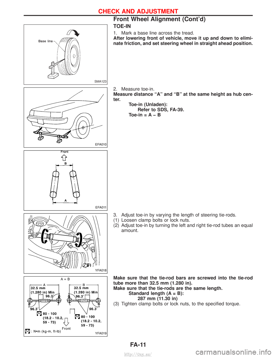
TOE-IN
1. Mark a base line across the tread.
After lowering front of vehicle, move it up and down to elimi-
nate friction, and set steering wheel in straight ahead position.
2. Measure toe-in.
Measure distance ªAº and ªBº at the same height as hub cen-
ter.Toe-in (Unladen):Refer to SDS, FA-39.
Toe-in = A þ B
3. Adjust toe-in by varying the length of steering tie-rods.
(1) Loosen clamp bolts or lock nuts.
(2) Adjust toe-in by turning the left and right tie-rod tubes an equal amount.
Make sure that the tie-rod bars are screwed into the tie-rod
tube more than 32.5 mm (1.280 in).
Make sure that the tie-rods are the same length. Standard length (A = B):287 mm (11.30 in)
(3) Tighten clamp bolts or lock nuts, to the specified torque.
SMA123
EFA010
EFA011
YFA018
YFA019
CHECK AND ADJUSTMENT
Front Wheel Alignment (Cont'd)
FA-11
http://vnx.su/
Page 1123 of 1833
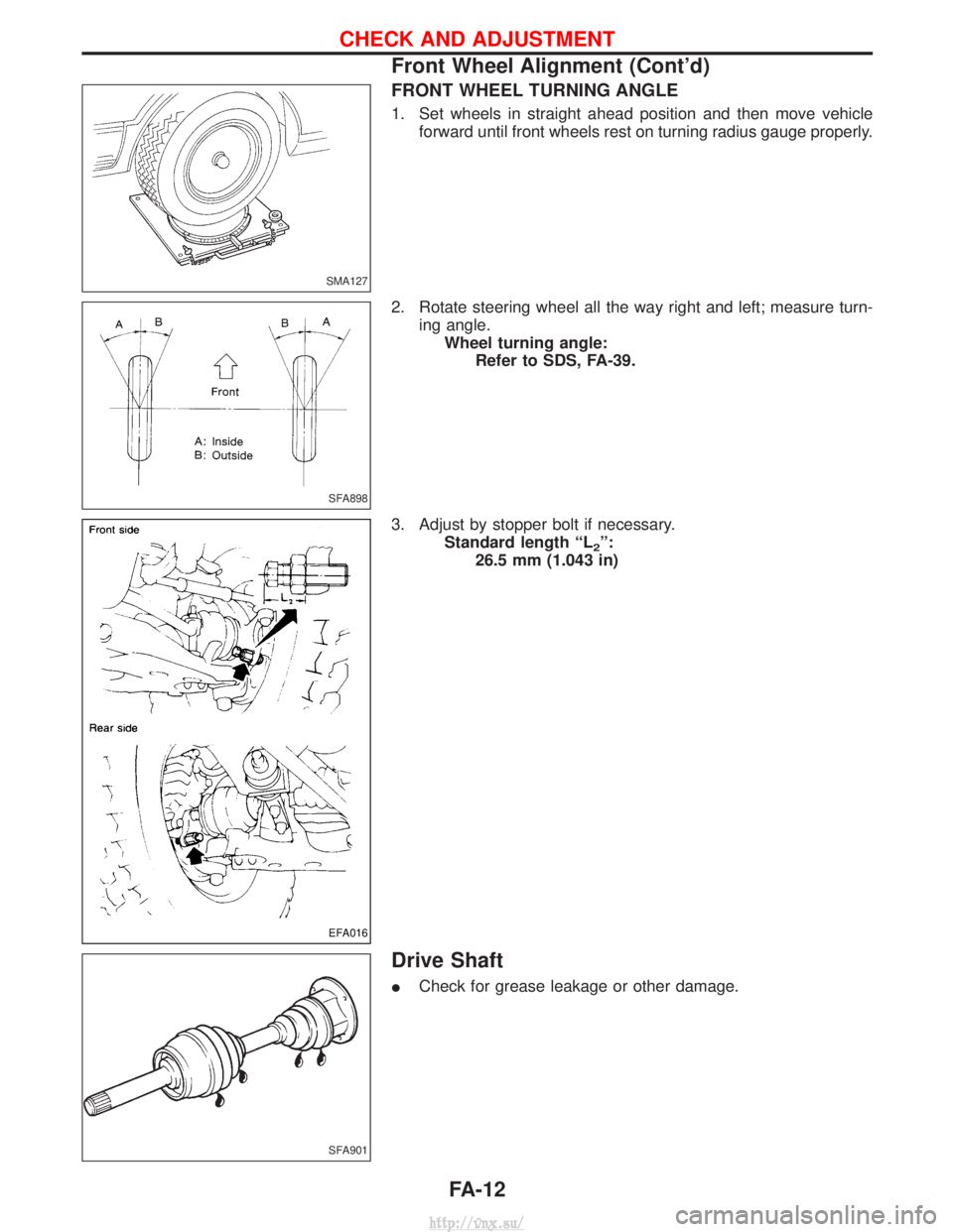
FRONT WHEEL TURNING ANGLE
1. Set wheels in straight ahead position and then move vehicleforward until front wheels rest on turning radius gauge properly.
2. Rotate steering wheel all the way right and left; measure turn- ing angle.Wheel turning angle: Refer to SDS, FA-39.
3. Adjust by stopper bolt if necessary. Standard length ªL
2º:
26.5 mm (1.043 in)
Drive Shaft
I Check for grease leakage or other damage.
SMA127
SFA898
EFA016
SFA901
CHECK AND ADJUSTMENT
Front Wheel Alignment (Cont'd)
FA-12
http://vnx.su/
Page 1170 of 1833
Supplement Restraint System (SRS) ªAIR BAGº
and ªSEAT BELT PRE-TENSIONERº
The Supplemental Restraint System ªAir Bagº and ªSeat Belt Pre-tensionerº, used along with a seat belt, help
to reduce the risk or severity or injury to the driver and front passenger in a collision. The Supplemental
Restraint System consists of an air bag module (located in the center of the steering wheel and on the instru-
ment panel on the passenger side, where fitted), seat belt pre-tensioners, a diagnosis sensor unit, warning
lamp, wiring harness and spiral cable. Information necessary to service the system safely is included in the
BT sectionof this Service Manual.
WARNING:
I To avoid rendering the SRS inoperative (which could increase the risk of personal injury or death
in the event of a collision which would result in air bag inflation), all maintenance must be per-
formed by an authorized NISSAN dealer.
I Improper maintenance, including incorrect removal and installation of the SRS, can lead to per-
sonal injury caused by unintentional activation of the system.
I Do not use electrical test equipment on any circuit related to the SRS unless instructed to in this
Service Manual. SRS wiring harnesses (except ªSEAT BELT-TENSIONERº connector) can be iden-
tified with yellow harness connector and with yellow harness protector or yellow insulation tape
before the harness connectors.
Precautions
IUse only ªDOT 4º fluid from a sealed container.
I Never reuse drained brake fluid.
I Be careful not to splash brake fluid on painted areas; it
may cause paint damage. If brake fluid is splashed on
painted areas, wash it away with water immediately.
I To clean master cylinder parts, disc brake caliper parts or
wheel cylinder parts, use clean brake fluid.
I Never use mineral oils such as Petrol or kerosene. They
will ruin rubber parts of hydraulic system.
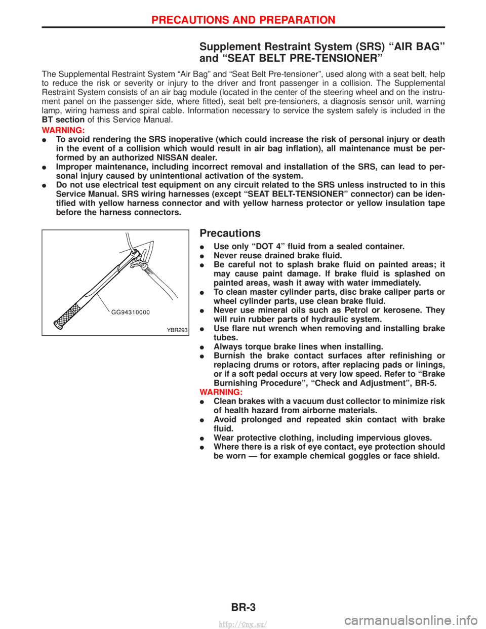
I Use flare nut wrench when removing and installing brake
tubes.
I Always torque brake lines when installing.
I Burnish the brake contact surfaces after refinishing or
replacing drums or rotors, after replacing pads or linings,
or if a soft pedal occurs at very low speed. Refer to ªBrake
Burnishing Procedureº, ªCheck and Adjustmentº, BR-5.
WARNING:
I Clean brakes with a vacuum dust collector to minimize risk
of health hazard from airborne materials.
I Avoid prolonged and repeated skin contact with brake
fluid.
I Wear protective clothing, including impervious gloves.
I Where there is a risk of eye contact, eye protection should
be worn Ð for example chemical goggles or face shield.
YBR293
PRECAUTIONS AND PREPARATION
BR-3
http://vnx.su/