2004 NISSAN TERRANO automatic transmission
[x] Cancel search: automatic transmissionPage 1014 of 1833
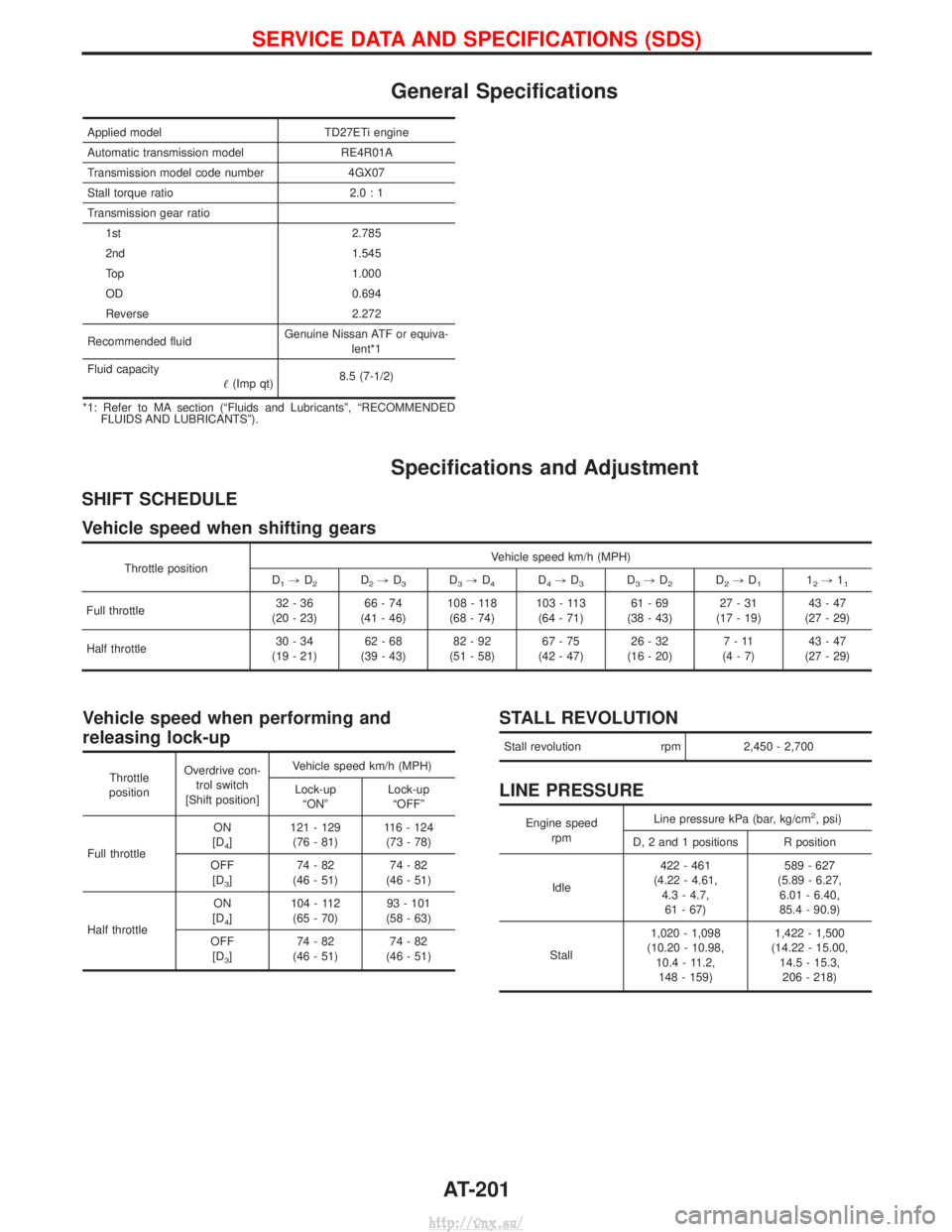
General Specifications
Applied modelTD27ETi engine
Automatic transmission model RE4R01A
Transmission model code number 4GX07
Stall torque ratio 2.0 : 1
Transmission gear ratio 1st 2.785
2nd 1.545
Top 1.000
OD 0.694
Reverse 2.272
Recommended fluid Genuine Nissan ATF or equiva-
lent*1
Fluid capacity (Imp qt) 8.5 (7-1/2)
*1: Refer to MA section (ªFluids and Lubricantsº, ªRECOMMENDED FLUIDS AND LUBRICANTSº).
Specifications and Adjustment
SHIFT SCHEDULE
Vehicle speed when shifting gears
Throttle position Vehicle speed km/h (MPH)
D1, D2D2,D3D3,D4D4,D3D3,D2D2,D112,11
Full throttle 32-36
(20 - 23) 66-74
(41 - 46) 108 - 118
(68 - 74) 103 - 113
(64 - 71) 61-69
(38 - 43) 27-31
(17 - 19) 43-47
(27 - 29)
Half throttle 30-34
(19 - 21) 62-68
(39 - 43) 82-92
(51 - 58) 67-75
(42 - 47) 26-32
(16 - 20) 7-11
(4-7) 43-47
(27 - 29)
Vehicle speed when performing and
releasing lock-up
Throttle
position Overdrive con-
trol switch
[Shift position] Vehicle speed km/h (MPH)
Lock-up ªONº Lock-up
ªOFFº
Full throttle ON
[D
4] 121 - 129
(76 - 81) 116 - 124
(73 - 78)
OFF [D
3] 74-82
(46 - 51) 74-82
(46 - 51)
Half throttle ON
[D
4] 104 - 112
(65 - 70) 93 - 101
(58 - 63)
OFF [D
3] 74-82
(46 - 51) 74-82
(46 - 51)
STALL REVOLUTION
Stall revolution rpm2,450 - 2,700
LINE PRESSURE
Engine speed
rpm Line pressure kPa (bar, kg/cm2, psi)
D, 2 and 1 positions R position
Idle 422 - 461
(4.22 - 4.61, 4.3 - 4.7,61 - 67) 589 - 627
(5.89 - 6.27, 6.01 - 6.40,
85.4 - 90.9)
Stall 1,020 - 1,098
(10.20 - 10.98, 10.4 - 11.2,148 - 159) 1,422 - 1,500
(14.22 - 15.00, 14.5 - 15.3,206 - 218)
SERVICE DATA AND SPECIFICATIONS (SDS)
AT-201
http://vnx.su/
Page 1255 of 1833
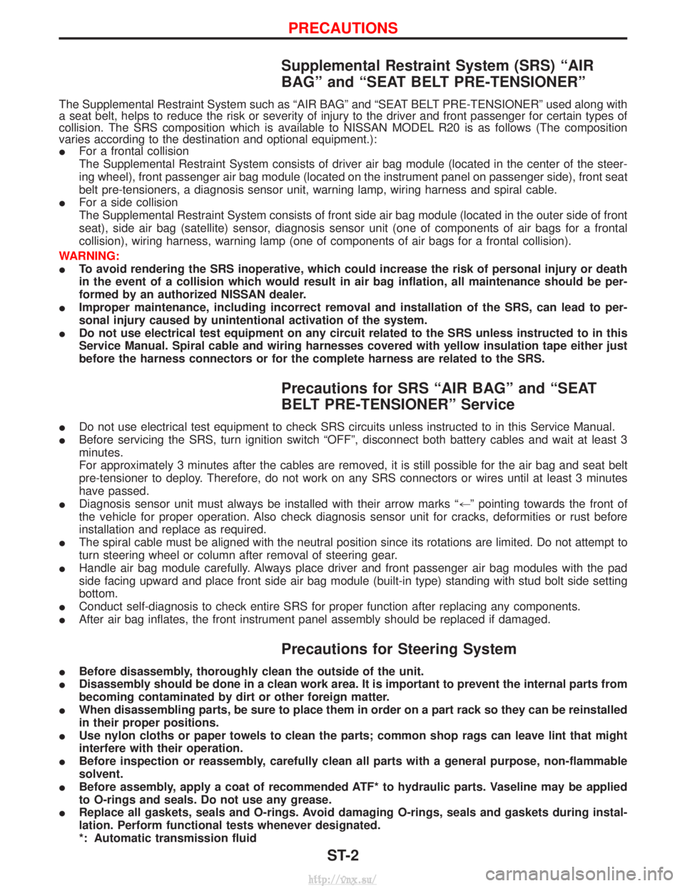
Supplemental Restraint System (SRS) ªAIR
BAGº and ªSEAT BELT PRE-TENSIONERº
The Supplemental Restraint System such as ªAIR BAGº and ªSEAT BELT PRE-TENSIONERº used along with
a seat belt, helps to reduce the risk or severity of injury to the driver and front passenger for certain types of
collision. The SRS composition which is available to NISSAN MODEL R20 is as follows (The composition
varies according to the destination and optional equipment.):
IFor a frontal collision
The Supplemental Restraint System consists of driver air bag module (located in the center of the steer-
ing wheel), front passenger air bag module (located on the instrument panel on passenger side), front seat
belt pre-tensioners, a diagnosis sensor unit, warning lamp, wiring harness and spiral cable.
I For a side collision
The Supplemental Restraint System consists of front side air bag module (located in the outer side of front
seat), side air bag (satellite) sensor, diagnosis sensor unit (one of components of air bags for a frontal
collision), wiring harness, warning lamp (one of components of air bags for a frontal collision).
WARNING:
I To avoid rendering the SRS inoperative, which could increase the risk of personal injury or death
in the event of a collision which would result in air bag inflation, all maintenance should be per-
formed by an authorized NISSAN dealer.
I Improper maintenance, including incorrect removal and installation of the SRS, can lead to per-
sonal injury caused by unintentional activation of the system.
I Do not use electrical test equipment on any circuit related to the SRS unless instructed to in this
Service Manual. Spiral cable and wiring harnesses covered with yellow insulation tape either just
before the harness connectors or for the complete harness are related to the SRS.
Precautions for SRS ªAIR BAGº and ªSEAT
BELT PRE-TENSIONERº Service
IDo not use electrical test equipment to check SRS circuits unless instructed to in this Service Manual.
I Before servicing the SRS, turn ignition switch ªOFFº, disconnect both battery cables and wait at least 3
minutes.
For approximately 3 minutes after the cables are removed, it is still possible for the air bag and seat belt
pre-tensioner to deploy. Therefore, do not work on any SRS connectors or wires until at least 3 minutes
have passed.
I Diagnosis sensor unit must always be installed with their arrow marks ª +º pointing towards the front of
the vehicle for proper operation. Also check diagnosis sensor unit for cracks, deformities or rust before
installation and replace as required.
I The spiral cable must be aligned with the neutral position since its rotations are limited. Do not attempt to
turn steering wheel or column after removal of steering gear.
I Handle air bag module carefully. Always place driver and front passenger air bag modules with the pad
side facing upward and place front side air bag module (built-in type) standing with stud bolt side setting
bottom.
I Conduct self-diagnosis to check entire SRS for proper function after replacing any components.
I After air bag inflates, the front instrument panel assembly should be replaced if damaged.
Precautions for Steering System
IBefore disassembly, thoroughly clean the outside of the unit.
I Disassembly should be done in a clean work area. It is important to prevent the internal parts from
becoming contaminated by dirt or other foreign matter.
I When disassembling parts, be sure to place them in order on a part rack so they can be reinstalled
in their proper positions.
I Use nylon cloths or paper towels to clean the parts; common shop rags can leave lint that might
interfere with their operation.
I Before inspection or reassembly, carefully clean all parts with a general purpose, non-flammable
solvent.
I Before assembly, apply a coat of recommended ATF* to hydraulic parts. Vaseline may be applied
to O-rings and seals. Do not use any grease.
I Replace all gaskets, seals and O-rings. Avoid damaging O-rings, seals and gaskets during instal-
lation. Perform functional tests whenever designated.
*: Automatic transmission fluid
PRECAUTIONS
ST-2
http://vnx.su/
Page 1827 of 1833
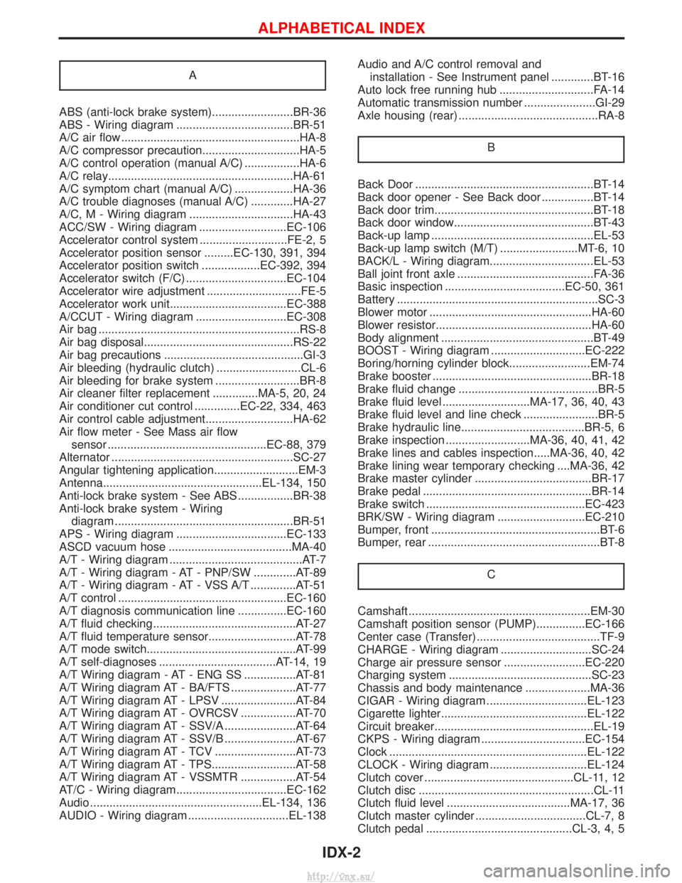
A
ABS (anti-lock brake system).........................BR-36
ABS - Wiring diagram ....................................BR-51
A/C air flow .......................................................HA-8
A/C compressor precaution..............................HA-5
A/C control operation (manual A/C) .................HA-6
A/C relay.........................................................HA-61
A/C symptom chart (manual A/C) ..................HA-36
A/C trouble diagnoses (manual A/C) .............HA-27
A/C, M - Wiring diagram ................................HA-43
ACC/SW - Wiring diagram ...........................EC-106
Accelerator control system ...........................FE-2, 5
Accelerator position sensor .........EC-130, 391, 394
Accelerator position switch ..................EC-392, 394
Accelerator switch (F/C) ...............................EC-104
Accelerator wire adjustment .............................FE-5
Accelerator work unit....................................EC-388
A/CCUT - Wiring diagram ............................EC-308
Air bag ..............................................................RS-8
Air bag disposal..............................................RS-22
Air bag precautions ...........................................GI-3
Air bleeding (hydraulic clutch) ..........................CL-6
Air bleeding for brake system ..........................BR-8
Air cleaner filter replacement ..............MA-5, 20, 24
Air conditioner cut control ..............EC-22, 334, 463
Air control cable adjustment...........................HA-62
Air flow meter - See Mass air flowsensor .................................................EC-88, 379
Alternator ........................................................SC-27
Angular tightening application..........................EM-3
Antenna.................................................EL-134, 150
Anti-lock brake system - See ABS .................BR-38
Anti-lock brake system - Wiring diagram .......................................................BR-51
APS - Wiring diagram ..................................EC-133
ASCD vacuum hose ......................................MA-40
A/T - Wiring diagram .........................................AT-7
A/T - Wiring diagram - AT - PNP/SW .............AT-89
A/T - Wiring diagram - AT - VSS A/T ..............AT-51
A/T control ....................................................EC-160
A/T diagnosis communication line ...............EC-160
A/T fluid checking ............................................AT-27
A/T fluid temperature sensor...........................AT-78
A/T mode switch..............................................AT-99
A/T self-diagnoses ....................................AT-14, 19
A/T Wiring diagram - AT - ENG SS ................AT-81
A/T Wiring diagram AT - BA/FTS ....................AT-77
A/T Wiring diagram AT - LPSV .......................AT-84
A/T Wiring diagram AT - OVRCSV .................AT-70
A/T Wiring diagram AT - SSV/A ......................AT-64
A/T Wiring diagram AT - SSV/B ......................AT-67
A/T Wiring diagram AT - TCV .........................AT-73
A/T Wiring diagram AT - TPS..........................AT-58
A/T Wiring diagram AT - VSSMTR .................AT-54
AT/C - Wiring diagram..................................EC-162
Audio .....................................................EL-134, 136
AUDIO - Wiring diagram ...............................EL-138 Audio and A/C control removal and
installation - See Instrument panel .............BT-16
Auto lock free running hub .............................FA-14
Automatic transmission number ......................GI-29
Axle housing (rear) ...........................................RA-8
B
Back Door .......................................................BT-14
Back door opener - See Back door ................BT-14
Back door trim.................................................BT-18
Back door window...........................................BT-43
Back-up lamp ..................................................EL-53
Back-up lamp switch (M/T) ........................MT-6, 10
BACK/L - Wiring diagram................................EL-53
Ball joint front axle ..........................................FA-36
Basic inspection .....................................EC-50, 361
Battery ..............................................................SC-3
Blower motor ..................................................HA-60
Blower resistor................................................HA-60
Body alignment ...............................................BT-49
BOOST - Wiring diagram .............................EC-222
Boring/horning cylinder block.........................EM-74
Brake booster .................................................BR-18
Brake fluid change ...........................................BR-5
Brake fluid level ...........................MA-17, 36, 40, 43
Brake fluid level and line check .......................BR-5
Brake hydraulic line......................................BR-5, 6
Brake inspection ..........................MA-36, 40, 41, 42
Brake lines and cables inspection.....MA-36, 40, 42
Brake lining wear temporary checking ....MA-36, 42
Brake master cylinder ....................................BR-17
Brake pedal ....................................................BR-14
Brake switch .................................................EC-423
BRK/SW - Wiring diagram ...........................EC-210
Bumper, front ....................................................BT-6
Bumper, rear .....................................................BT-8C
Camshaft ........................................................EM-30
Camshaft position sensor (PUMP)...............EC-166
Center case (Transfer) ......................................TF-9
CHARGE - Wiring diagram ............................SC-24
Charge air pressure sensor .........................EC-220
Charging system ............................................SC-23
Chassis and body maintenance ....................MA-36
CIGAR - Wiring diagram ...............................EL-123
Cigarette lighter.............................................EL-122
Circuit breaker.................................................EL-19
CKPS - Wiring diagram ................................EC-154
Clock .............................................................EL-122
CLOCK - Wiring diagram ..............................EL-124
Clutch cover ..............................................CL-11, 12
Clutch disc ......................................................CL-11
Clutch fluid level ......................................MA-17, 36
Clutch master cylinder ..................................CL-7, 8
Clutch pedal .............................................CL-3, 4, 5
ALPHABETICAL INDEX
IDX-2
http://vnx.su/