Page 126 of 1833
Inspection
IWhen the camshaft or parts in connection with valves are
removed or replaced, and a fault has occurred (poor starting,
idling, or other faults) due to the misadjustment of the valve
clearance, inspect as follows.
I Inspect and adjust when the engine is cool (at normal tempera-
ture).
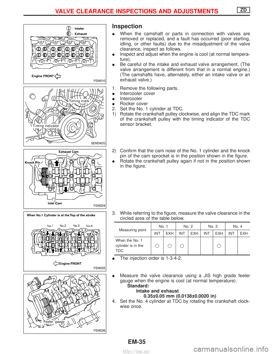
I Be careful of the intake and exhaust valve arrangement. (The
valve arrangement is different from that in a normal engine.)
(The camshafts have, alternately, either an intake valve or an
exhaust valve.)
1. Remove the following parts.
I Intercooler cover
I Intercooler
I Rocker cover
2. Set the No. 1 cylinder at TDC.
1) Rotate the crankshaft pulley clockwise, and align the TDC mark of the crankshaft pulley with the timing indicator of the TDC
sensor bracket.
2) Confirm that the cam nose of the No. 1 cylinder and the knock pin of the cam sprocket is in the position shown in the figure.
I Rotate the crankshaft pulley again if not in the position shown
in the figure.
3. While referring to the figure, measure the valve clearance in the circled area of the table below.
Measuring point No. 1 No. 2 No. 3 No. 4
INT EXH INT EXH INT EXH INT EXH
When the No. 1
cylinder is in the
TDC qqq q
I
The injection order is 1-3-4-2.
I Measure the valve clearance using a JIS high grade feeler
gauge when the engine is cool (at normal temperature).
Standard: Intake and exhaust0.35 0.05 mm (0.0138 0.0020 in)
4. Set the No. 4 cylinder at TDC by rotating the crankshaft clock- wise once.
FEM010
SEM342G
FEM024
FEM025
FEM026
VALVE CLEARANCE INSPECTIONS AND ADJUSTMENTSZD
EM-35
http://vnx.su/
Page 127 of 1833

5. While referring to the figure, measure the valve clearance in thecircled area of the table below.
Measuring point No. 1 No. 2 No. 3 No. 4
INT EXH INT EXH INT EXH INT EXH
When the No. 4
cylinder is in the
TDC qq qq
6. If the valve clearance is outside the specification, adjust as fol-
lows.
Adjustments
IRemove the adjusting shim for parts which are outside the
specified valve clearance.
1. Remove the spill tube.
2. Extract the engine oil on the upper side of the cylinder head (for the air gun used in step 7).
3. Rotate the crankshaft to face the cam for adjusting shims that are to be removed upward.
4. Grip the camshaft with camshaft pliers (SST), the using the camshaft as a support point, push the adjusting shim downward
to compress the valve spring.
CAUTION:
Do not damage the camshaft, cylinder head, or the outer cir-
cumference of the valve lifter.
5. With the valve spring in a compressed state, remove the cam- shaft pliers (SST) by securely setting the outer circumference
of the valve lifter with the end of the lifter stopper (SST).
I Hold the lifter stopper by hand until the shim is removed.
CAUTION:
Do not retrieve the camshaft pliers forcefully, as the camshaft
will be damaged.
6. Move the rounded hole of the adjusting shim to the front with a very thin screwdriver.
I When the adjusting shim on the valve lifter will not rotate
smoothly, restart from step 4 with the end of the lifter stopper
(SST) touching the adjusting shim.
7. Remove the adjusting shim from the valve lifter by blowing air through the rounded hole of the shim with an air gun.
CAUTION:
To prevent any remaining oil from being blown around, thor-
oughly wipe the area clean and wear protective goggles.
FEM027
FEM028
FEM029
FEM030
VALVE CLEARANCE INSPECTIONS AND ADJUSTMENTSZD
Inspection (Cont'd)
EM-36
http://vnx.su/
Page 128 of 1833
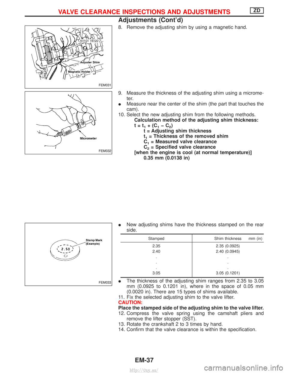
8. Remove the adjusting shim by using a magnetic hand.
9. Measure the thickness of the adjusting shim using a microme-ter.
I Measure near the center of the shim (the part that touches the
cam).
10. Select the new adjusting shim from the following methods. Calculation method of the adjusting shim thickness:
t=t
1+(C1þC2)
t = Adjusting shim thickness
t
1= Thickness of the removed shim
C
1= Measured valve clearance
C
2= Specified valve clearance
[when the engine is cool (at normal temperature)] 0.35 mm (0.0138 in)
I New adjusting shims have the thickness stamped on the rear
side.
Stamped Shim thickness mm (in)
2.35
2.40 .
.
.
3.05 2.35 (0.0925)
2.40 (0.0945)
.
.
.
3.05 (0.1201)
I The thickness of the adjusting shim ranges from 2.35 to 3.05
mm (0.0925 to 0.1201 in), where in the space of 0.05 mm
(0.0020 in). There are 15 types of shims available.
11. Fix the selected adjusting shim to the valve lifter.
CAUTION:
Place the stamped side of the adjusting shim to the valve lifter.
12. Compress the valve spring using the camshaft pliers and remove the lifter stopper (SST).
13. Rotate the crankshaft 2 to 3 times by hand.
14. Confirm that the valve clearance is within the specification.
FEM031
FEM032
FEM033
VALVE CLEARANCE INSPECTIONS AND ADJUSTMENTSZD
Adjustments (Cont'd)
EM-37
http://vnx.su/
Page 148 of 1833
8. Install oil return pipe to the rear side of the cylinder head.
IWhen reinstalling a stud bolt, apply Three Bond 1207C (KP510
00150) to the thread of the bolt.
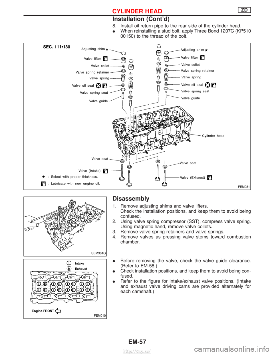
Disassembly
1. Remove adjusting shims and valve lifters.
Check the installation positions, and keep them to avoid being
confused.
2. Using valve spring compressor (SST), compress valve spring. Using magnetic hand, remove valve collets.
3. Remove valve spring retainers and valve springs.
4. Remove valves as pressing valve stems toward combustion chamber.
I Before removing the valve, check the valve guide clearance.
(Refer to EM-58.)
I Check installation positions, and keep them to avoid being con-
fused.
I Refer to the figure for intake/exhaust valve positions. (Intake
and exhaust valve driving cams are provided alternately for
each camshaft.)
FEM081
SEM361G
FEM010
CYLINDER HEADZD
Installation (Cont'd)
EM-57
http://vnx.su/
Page 149 of 1833
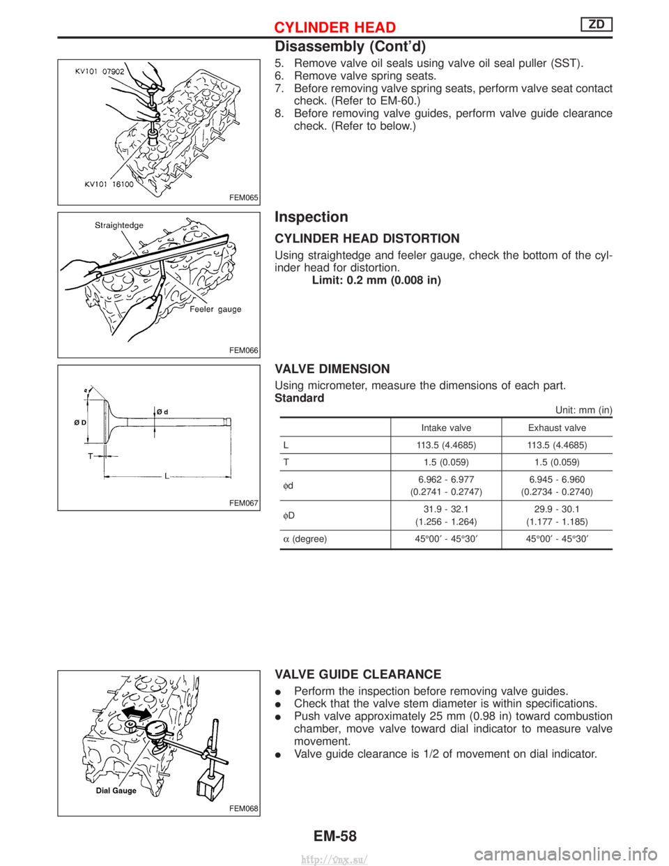
5. Remove valve oil seals using valve oil seal puller (SST).
6. Remove valve spring seats.
7. Before removing valve spring seats, perform valve seat contactcheck. (Refer to EM-60.)
8. Before removing valve guides, perform valve guide clearance check. (Refer to below.)
Inspection
CYLINDER HEAD DISTORTION
Using straightedge and feeler gauge, check the bottom of the cyl-
inder head for distortion. Limit: 0.2 mm (0.008 in)
VALVE DIMENSION
Using micrometer, measure the dimensions of each part.
Standard
Unit: mm (in)
Intake valve Exhaust valve
L 113.5 (4.4685)113.5 (4.4685)
T 1.5 (0.059)1.5 (0.059)
f d 6.962 - 6.977
(0.2741 - 0.2747) 6.945 - 6.960
(0.2734 - 0.2740)
f D 31.9 - 32.1
(1.256 - 1.264) 29.9 - 30.1
(1.177 - 1.185)
a (degree) 45É00¢- 45É30¢ 45É00¢- 45É30¢
VALVE GUIDE CLEARANCE
IPerform the inspection before removing valve guides.
I Check that the valve stem diameter is within specifications.
I Push valve approximately 25 mm (0.98 in) toward combustion
chamber, move valve toward dial indicator to measure valve
movement.
I Valve guide clearance is 1/2 of movement on dial indicator.
FEM065
FEM066
FEM067
FEM068
CYLINDER HEADZD
Disassembly (Cont'd)
EM-58
http://vnx.su/
Page 152 of 1833
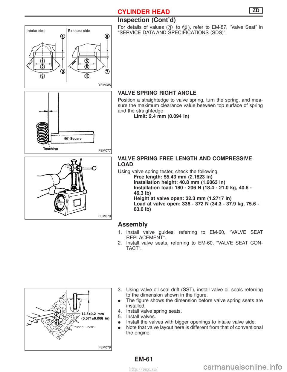
For details of values (q1toq10), refer to EM-87, ªValve Seatº in
ªSERVICE DATA AND SPECIFICATIONS (SDS)º.
VALVE SPRING RIGHT ANGLE
Position a straightedge to valve spring, turn the spring, and mea-
sure the maximum clearance value between top surface of spring
and the straightedge Limit: 2.4 mm (0.094 in)
VALVE SPRING FREE LENGTH AND COMPRESSIVE
LOAD
Using valve spring tester, check the following.Free length: 55.43 mm (2.1823 in)
Installation height: 40.8 mm (1.6063 in)
Installation load: 180 - 206 N (18.4 - 21.0 kg, 40.6 -
46.3 lb)
Height at valve open: 32.3 mm (1.2717 in)
Load at valve open: 336 - 372 N (34.3 - 37.9 kg, 75.6 -
83.6 lb)
Assembly
1. Install valve guides, referring to EM-60, ªVALVE SEATREPLACEMENTº.
2. Install valve seats, referring to EM-60, ªVALVE SEAT CON- TACTº.
3. Using valve oil seal drift (SST), install valve oil seals referring to the dimension shown in the figure.
I The figure shows the dimension before valve spring seats are
installed.
4. Install valve spring seats.
5. Install valves.
I Install the valves with bigger openings to intake valve side.
I Note that valve layout here is different from that of conventional
the engine.
YEM035
FEM077
FEM078
FEM079
CYLINDER HEADZD
Inspection (Cont'd)
EM-61
http://vnx.su/
Page 176 of 1833
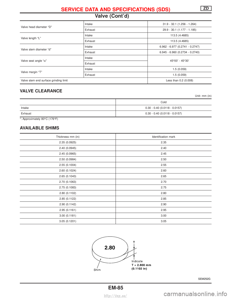
Valve head diameter ªDºIntake 31.9 - 32.1 (1.256 - 1.264)
Exhaust 29.9 - 30.1 (1.177 - 1.185)
Valve length ªLº Intake 113.5 (4.4685)
Exhaust 113.5 (4.4685)
Valve stem diameter ªdº Intake 6.962 - 6.977 (0.2741 - 0.2747)
Exhaust 6.945 - 6.960 (0.2734 - 0.2740)
Valve seat angle ªa º Intake
45É00¢- 45É30¢
Exhaust
Valve margin ªTº Intake 1.5 (0.059)
Exhaust 1.5 (0.059)
Valve stem end surface grinding limit Less than 0.2 (0.008)
VALVE CLEARANCE
Unit: mm (in)
Cold
Intake 0.30 - 0.40 (0.0118 - 0.0157)
Exhaust 0.30 - 0.40 (0.0118 - 0.0157)
*: Approximately 80ÉC (176ÉF)
AVAILABLE SHIMS
Thickness mm (in) Identification mark
2.35 (0.0925) 2.35
2.40 (0.0945) 2.40
2.45 (0.0965) 2.45
2.50 (0.0984) 2.50
2.55 (0.1004) 2.55
2.60 (0.1024) 2.60
2.65 (0.1043) 2.65
2.70 (0.1063) 2.70
2.75 (0.1083) 2.75
2.80 (0.1102) 2.80
2.85 (0.1122) 2.85
2.90 (0.1142) 2.90
2.95 (0.1161) 2.95
3.00 (0.1181) 3.00
3.05 (0.1201) 3.05
SEM252G
SERVICE DATA AND SPECIFICATIONS (SDS)ZD
Valve (Cont'd)
EM-85
http://vnx.su/
Page 177 of 1833
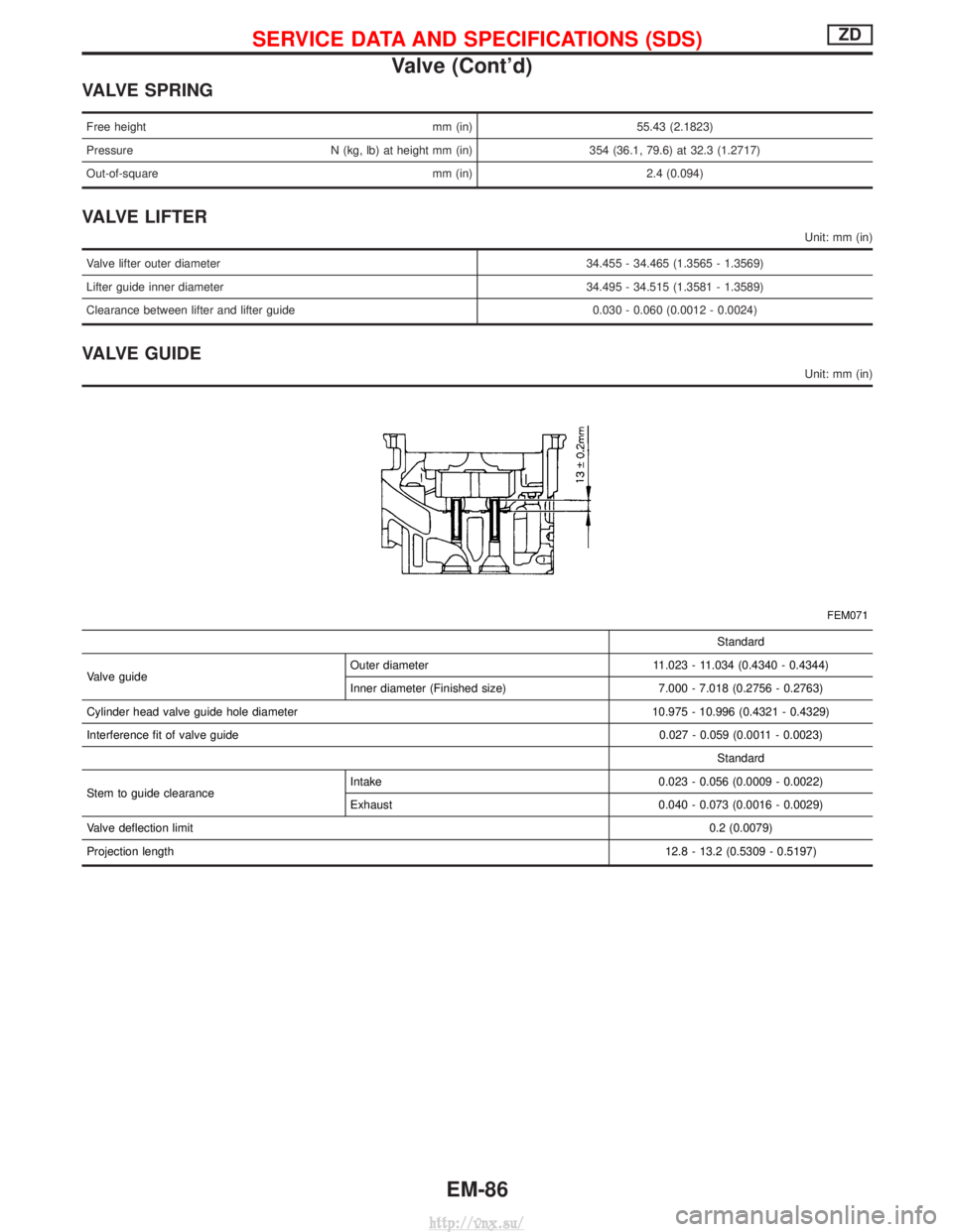
VALVE SPRING
Free heightmm (in)55.43 (2.1823)
Pressure N (kg, lb) at height mm (in) 354 (36.1, 79.6) at 32.3 (1.2717)
Out-of-square mm (in) 2.4 (0.094)
VALVE LIFTER
Unit: mm (in)
Valve lifter outer diameter 34.455 - 34.465 (1.3565 - 1.3569)
Lifter guide inner diameter 34.495 - 34.515 (1.3581 - 1.3589)
Clearance between lifter and lifter guide 0.030 - 0.060 (0.0012 - 0.0024)
VALVE GUIDE
Unit: mm (in)
FEM071
Standard
Valve guide Outer diameter 11.023 - 11.034 (0.4340 - 0.4344)
Inner diameter (Finished size) 7.000 - 7.018 (0.2756 - 0.2763)
Cylinder head valve guide hole diameter 10.975 - 10.996 (0.4321 - 0.4329)
Interference fit of valve guide 0.027 - 0.059 (0.0011 - 0.0023)
Standard
Stem to guide clearance Intake 0.023 - 0.056 (0.0009 - 0.0022)
Exhaust 0.040 - 0.073 (0.0016 - 0.0029)
Valve deflection limit 0.2 (0.0079)
Projection length 12.8 - 13.2 (0.5309 - 0.5197)
SERVICE DATA AND SPECIFICATIONS (SDS)ZD
Valve (Cont'd)
EM-86
http://vnx.su/