Page 67 of 1833

Checking Idle Speed
Preparation
1. Make sure that injection timing is correct.
2. Make sure that injection nozzle are in good condition.
3. Make sure that the following parts are in good condition.
IAir cleaner clogging
I Glow system
I Engine oil and coolant levels
I Valve clearance
I Air intake system (Oil filler cap, oil level gauge, etc.)
4. Set shift lever in ªNeutralº position. Engage parking brake and lock both front and rear wheels with wheel chocks.
5. Turn off air conditioner, lights and accessories.
I Warm up engine until water temperature indicator points to middle of gauge.
I Lights, heater fan and all accessories are off.
I Attach tachometer's pick-up to No. 1 fuel injection tube.
In order to take accurate reading of engine rpm, remove clamps that secure No. 1 fuel injection tube.
Start engine.
SMA406B
SMA021A
Run engine at about 2,000 rpm for
about 2 minutes under no-load.
Run engine for one minute at idle
speed.F
Check idle speed.
---------------------------------------------------------------------------------------------------------------------------------------------------------------------------------------------------------------------------------- IDLE SPEED: 700+ 50 rpm
OK
ENG Adjust idle speed by turning idle speed adjust-
ing screw.
EMA049
END
I
Race engine two or three times and allow engine to return to idle speed. If idle speed is not within
the specified range, check acceleration linkage for binding and correct it if necessary.
H
H
H
H
H
ENGINE MAINTENANCETD
MA-26
http://vnx.su/
Page 156 of 1833

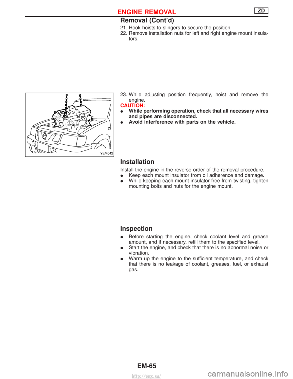
21. Hook hoists to slingers to secure the position.
22. Remove installation nuts for left and right engine mount insula-tors.
23. While adjusting position frequently, hoist and remove the engine.
CAUTION:
I While performing operation, check that all necessary wires
and pipes are disconnected.
I Avoid interference with parts on the vehicle.
Installation
Install the engine in the reverse order of the removal procedure.
IKeep each mount insulator from oil adherence and damage.
I While keeping each mount insulator free from twisting, tighten
mounting bolts and nuts for the engine mount.
Inspection
IBefore starting the engine, check coolant level and grease
amount, and if necessary, refill them to the specified level.
I Start the engine, and check that there is no abnormal noise or
vibration.
I Warm up the engine to the sufficient temperature, and check
that there is no leakage of coolant, greases, fuel, or exhaust
gas.
YEM042
ENGINE REMOVALZD
Removal (Cont'd)
EM-65
http://vnx.su/
Page 182 of 1833

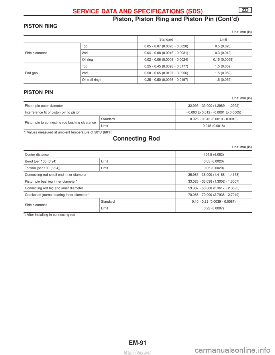
PISTON RING
Unit: mm (in)
StandardLimit
Side clearance Top
0.05 - 0.07 (0.0020 - 0.0028) 0.5 (0.020)
2nd 0.04 - 0.08 (0.0016 - 0.0031) 0.3 (0.012)
Oil ring 0.02 - 0.06 (0.0008 - 0.0024) 0.15 (0.0059)
End gap Top
0.25 - 0.45 (0.0098 - 0.0177) 1.5 (0.059)
2nd 0.50 - 0.65 (0.0197 - 0.0256) 1.5 (0.059)
Oil (rail ring) 0.25 - 0.50 (0.0098 - 0.0197) 1.5 (0.059)
PISTON PIN
Unit: mm (in)
Piston pin outer diameter 32.993 - 33.000 (1.2989 - 1.2992)
Interference fit of piston pin to piston þ0.003 to 0.012 (þ0.0001 to 0.0005)
Piston pin to connecting rod bushing clearance Standard 0.025 - 0.045 (0.0010 - 0.0018)
Limit 0.045 (0.0018)
*: Values measured at ambient temperature of 20ÉC (68ÉF)
Connecting Rod
Unit: mm (in)
Center distance 154.5 (6.083)
Bend [per 100 (3.94)] Limit 0.05 (0.0020)
Torsion [per 100 (3.94)] Limit 0.05 (0.0020)
Connecting rod small end inner diameter 35.987 - 36.000 (1.4168 - 1.4173)
Piston pin bushing inner diameter* 33.025 - 33.038 (1.3002 - 1.3007)
Connecting rod big end inner diameter 59.987 - 60.000 (2.3617 - 2.3622)
Crankshaft journal bearing inner diameter* 70.955 - 70.990 (2.7935 - 2.7949)
Side clearance Standard 0.10 - 0.22 (0.0039 - 0.0087)
Limit 0.22 (0.0087)
*: After installing in connecting rod
SERVICE DATA AND SPECIFICATIONS (SDS)ZD
Piston, Piston Ring and Piston Pin (Cont'd)
EM-91
http://vnx.su/
Page 196 of 1833

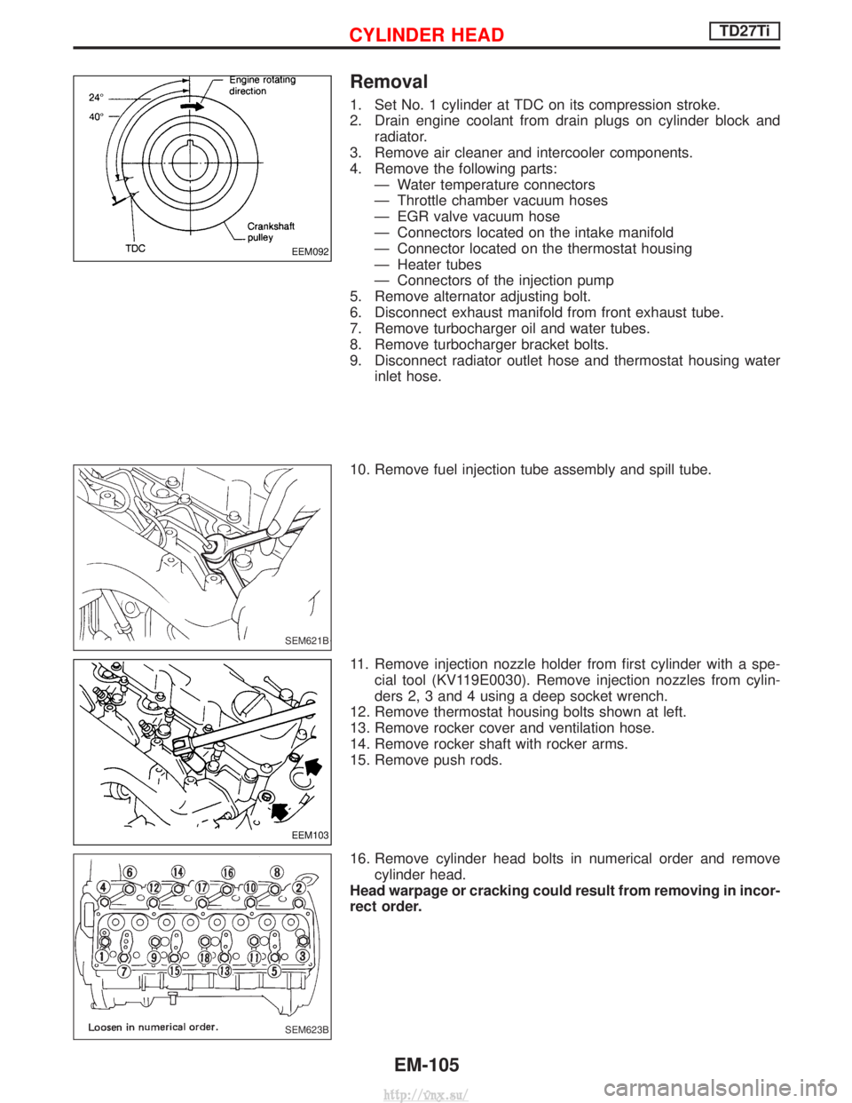
Removal
1. Set No. 1 cylinder at TDC on its compression stroke.
2. Drain engine coolant from drain plugs on cylinder block andradiator.
3. Remove air cleaner and intercooler components.
4. Remove the following parts: Ð Water temperature connectors
Ð Throttle chamber vacuum hoses
Ð EGR valve vacuum hose
Ð Connectors located on the intake manifold
Ð Connector located on the thermostat housing
Ð Heater tubes
Ð Connectors of the injection pump
5. Remove alternator adjusting bolt.
6. Disconnect exhaust manifold from front exhaust tube.
7. Remove turbocharger oil and water tubes.
8. Remove turbocharger bracket bolts.
9. Disconnect radiator outlet hose and thermostat housing water inlet hose.
10. Remove fuel injection tube assembly and spill tube.
11. Remove injection nozzle holder from first cylinder with a spe- cial tool (KV119E0030). Remove injection nozzles from cylin-
ders 2, 3 and 4 using a deep socket wrench.
12. Remove thermostat housing bolts shown at left.
13. Remove rocker cover and ventilation hose.
14. Remove rocker shaft with rocker arms.
15. Remove push rods.
16. Remove cylinder head bolts in numerical order and remove cylinder head.
Head warpage or cracking could result from removing in incor-
rect order.
EEM092
SEM621B
EEM103
SEM623B
CYLINDER HEADTD27Ti
EM-105
http://vnx.su/
Page 245 of 1833
Oil Pressure Check
WARNING:
IBe careful not to burn yourself, as the engine and oil may
be hot.
I Oil pressure check should be done in ªNeutralº gear posi-
tion.
1. Check oil level.
2. Remove oil pressure switch.
3. Install pressure gauge.
4. Start engine and warm it up to normal operating temperature.
5. Check oil pressure with engine running under no-load.
Engine speed
rpm Approximate discharge pressure
kPa (bar, kg/cm2, psi)
Idle speed 2,000
4,000 More than 147 (1.47, 1.5, 21)
More than 539 (5.39, 5.5, 78)
More than 736 (7.36, 7.5, 107)
If difference is extreme, check oil passage and oil pump.
6. Install oil pressure switch with sealant. Oil pressure switch:
:13-17N ×m (1.25 - 1.75 kg-m ,9-12ft-lb)
SLC694A
JLC362B
ENGINE LUBRICATION SYSTEMZD
LC-4
http://vnx.su/
Page 258 of 1833

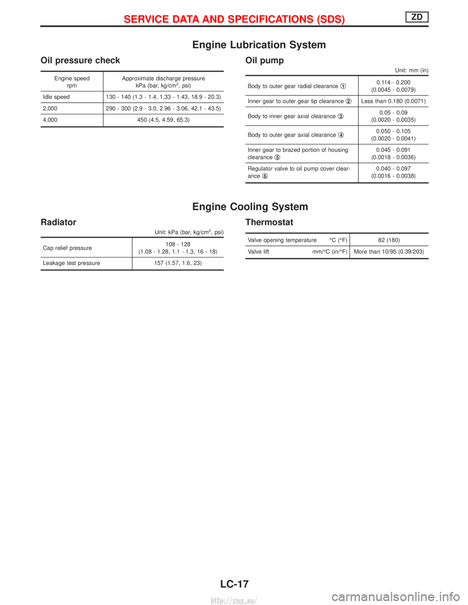
Engine Lubrication System
Oil pressure check
Engine speedrpm Approximate discharge pressure
kPa (bar, kg/cm2, psi)
Idle speed 130 - 140 (1.3 - 1.4, 1.33 - 1.43, 18.9 - 20.3)
2,000 290 - 300 (2.9 - 3.0, 2.96 - 3.06, 42.1 - 43.5)
4,000 450 (4.5, 4.59, 65.3)
Oil pump
Unit: mm (in)
Body to outer gear radial clearance q10.114 - 0.200
(0.0045 - 0.0079)
Inner gear to outer gear tip clearance q
2Less than 0.180 (0.0071)
Body to inner gear axial clearance q
30.05 - 0.09
(0.0020 - 0.0035)
Body to outer gear axial clearance q
40.050 - 0.105
(0.0020 - 0.0041)
Inner gear to brazed portion of housing
clearance q
50.045 - 0.091
(0.0018 - 0.0036)
Regulator valve to oil pump cover clear-
ance q
60.040 - 0.097
(0.0016 - 0.0038)
Engine Cooling System
Radiator
Unit: kPa (bar, kg/cm2, psi)
Cap relief pressure 108 - 128
(1.08 - 1.28, 1.1 - 1.3, 16 - 18)
Leakage test pressure 157 (1.57, 1.6, 23)
Thermostat
Valve opening temperature ÉC (ÉF) 82 (180)
Valve lift mm/ÉC (in/ÉF) More than 10/95 (0.39/203)
SERVICE DATA AND SPECIFICATIONS (SDS)ZD
LC-17
http://vnx.su/
Page 262 of 1833
Oil Pressure Check
WARNING:
IBe careful not to burn yourself, as the engine and oil may
be hot.
I Oil pressure check should be done in ªNeutralº gear posi-
tion.
1. Check oil level.
2. Remove oil pressure switch.
3. Install pressure gauge.
4. Start engine and warm it up to normal operating temperature.
5. Check oil pressure with engine running under no-load.
Engine rpm Approximate discharge pressure
kPa (bar, kg/cm2, psi)
Idle speed More than 78 (0.78, 0.8, 11) 3,000 294 - 392 (2.94 - 3.92, 3.0 - 4.0, 43 - 57)
If difference is extreme, check oil passage and oil pump for oil
leaks.
6. Install oil pressure switch.
Use proper liquid sealant. Oil pressure switch:
:10-13N ×m (1.0 - 1.3 kg-m, 87 - 113 in-lb)
SLC964
SLC003A
ENGINE LUBRICATION SYSTEMTD27Ti
LC-21
http://vnx.su/
Page 275 of 1833
Engine Lubrication System
Oil pressure check
Engine rpmApproximate discharge pressure
kPa (bar, kg/cm2, psi)
Idle speed More than 78 (0.78, 0.8, 11)
3,000 294 - 392 (2.94 - 3.92, 3.0 - 4.0, 43 - 57)
Oil pump
Unit: mm (in)
Gear side clearance Less than 0.13 (0.0051)
Gear backlash Less than 0.43 (0.0169)
Oil pump bushing clearance Less than 0.15 (0.0059)
Oil pump bushing inside diameter 13.012 - 13.098
(0.5123 - 0.5157)
Drive gear shaft outside diameter 12.974 - 12.992
(0.5108 - 0.5115)
Engine Cooling System
Thermostat
Valve opening temperature ÉC (ÉF)88 (190)
Max. Valve lift mm/ÉC (in/ÉF) 8/100
(0.315/212)
Radiator
Unit: kPa (bar, kg/cm2, psi)
Cap relief pressure 78-98
(0.78 - 0.98, 0.8 - 1.0, 11 - 14)
Leakage test pressure 157 (1.57, 1.6, 23)
SERVICE DATA AND SPECIFICATIONS (SDS)TD27Ti
LC-34
http://vnx.su/