2004 NISSAN TERRANO oil change
[x] Cancel search: oil changePage 856 of 1833
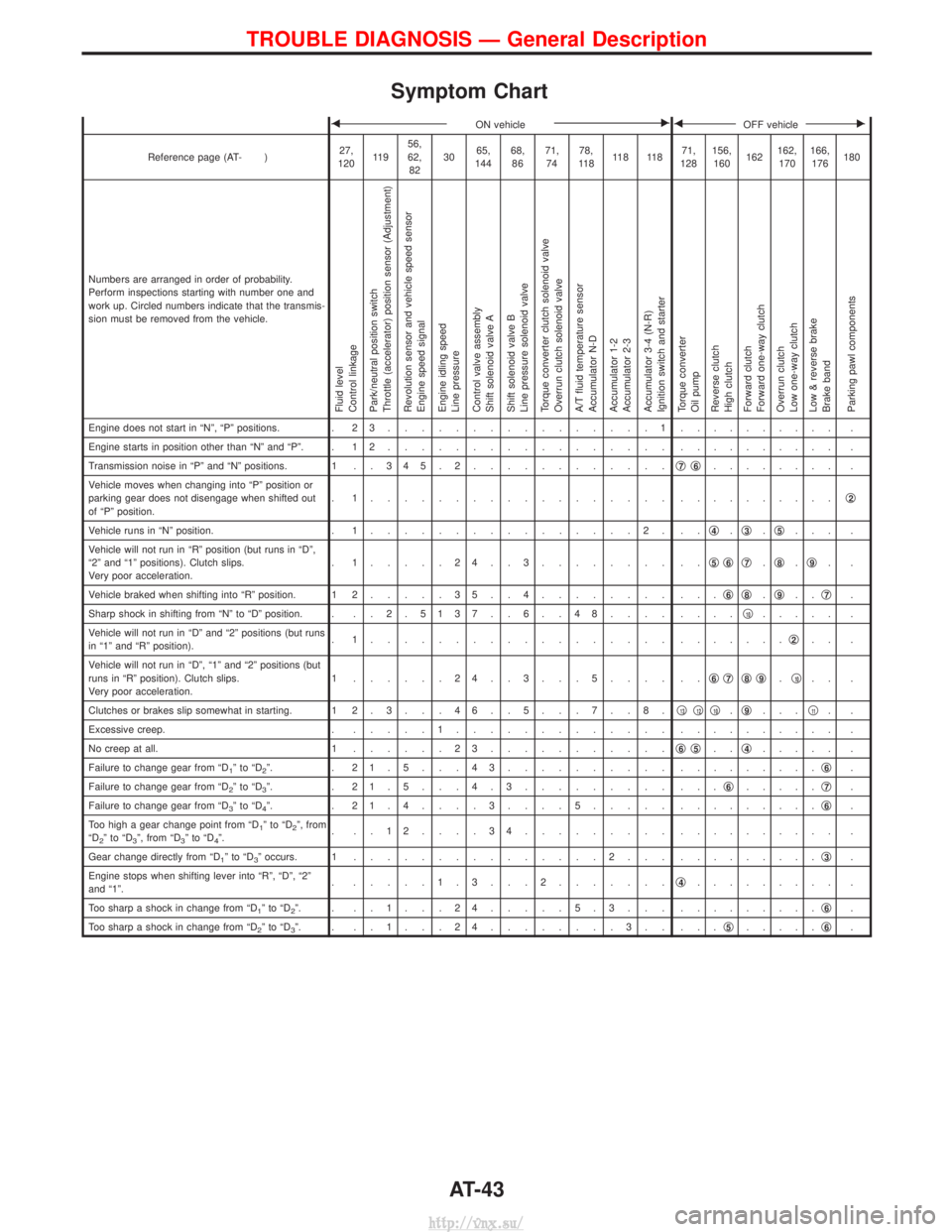
Symptom Chart
FON vehicleEFOFF vehicleE
Reference page (AT- )27,
120 11 9 56,
62,
82 30
65,
144 68,
86 71,
74 78,
11 8 11 8 11 8 71,
128 156,
160 162162,
170 166,
176 180
Numbers are arranged in order of probability.
Perform inspections starting with number one and
work up. Circled numbers indicate that the transmis-
sion must be removed from the vehicle.
Fluid level
Control linkage
Park/neutral position switch
Throttle (accelerator) position sensor (Adjustment)
Revolution sensor and vehicle speed sensor
Engine speed signal
Engine idling speed
Line pressure
Control valve assembly
Shift solenoid valve A
Shift solenoid valve B
Line pressure solenoid valve
Torque converter clutch solenoid valve
Overrun clutch solenoid valve
A/T fluid temperature sensor
Accumulator N-D
Accumulator 1-2
Accumulator 2-3
Accumulator 3-4 (N-R)
Ignition switch and starter
Torque converter
Oil pump
Reverse clutch
High clutch
Forward clutch
Forward one-way clutch
Overrun clutch
Low one-way clutch
Low & reverse brake
Brake band
Parking pawl components
Engine does not start in ªNº, ªPº positions. . 2 3................1. ......... .
Engine starts in position other than ªNº and ªPº. . 1 2 ................. . ......... .
Transmission noise in ªPº and ªNº positions. 1 . . 3 4 5 . 2 ............q
7q6........ .
Vehicle moves when changing into ªPº position or
parking gear does not disengage when shifted out
of ªPº position. . 1.................. .
.........q
2
Vehicle runs in ªNº position.
. 1................2. .. q4.q3.q5... .
Vehicle will not run in ªRº position (but runs in ªDº,
ª2º and ª1º positions). Clutch slips.
Very poor acceleration. . 1.....24..3........ ..
q
5q6q7.q8.q9..
Vehicle braked when shifting into ªRº position. 1 2 .....35..4........ ... q
6q8.q9.. q7.
Sharp shock in shifting from ªNº to ªDº position. . . . 2 . 5137 . . 6 . . 48.... ....q
10..... .
Vehicle will not run in ªDº and ª2º positions (but runs
in ª1º and ªRº position). . 1.................. .
......q
2.. .
Vehicle will not run in ªDº, ª1º and ª2º positions (but
runs in ªRº position). Clutch slips.
Very poor acceleration. 1 ......24..3...5.... ..
q
6q7q8q9.q10.. .
Clutches or brakes slip somewhat in starting. 1 2 . 3 . . . 4 6 . . 5 . . . 7 . . 8 . q
13q12q10.q9... q11..
Excessive creep. . .....1............. . ......... .
No creep at all. 1 ......23........... q
6q5..q4..... .
Failure to change gear from ªD
1ºtoªD2º. . 21.5...43.......... . ........q6.
Failure to change gear from ªD
2ºtoªD3º. . 21.5...4.3......... ... q6.....q7.
Failure to change gear from ªD
3ºtoªD4º. . 21.4....3....5..... . ........q6.
Too high a gear change point from ªD
1ºtoªD2º, from
ªD2ºtoªD3º, from ªD3ºtoªD4º. . ..12....34......... .
......... .
Gear change directly from ªD
1ºtoªD3º occurs. 1 ...............2... . ........q3.
Engine stops when shifting lever into ªRº, ªDº, ª2º
and ª1º. . .....1.3...2.......
q
4......... .
Too sharp a shock in change from ªD
1ºtoªD2º. . ..1...24.....5.3... . ........q6.
Too sharp a shock in change from ªD
2ºtoªD3º. . ..1...24........3.. ... q5.....q6.
TROUBLE DIAGNOSIS Ð General Description
AT-43
http://vnx.su/
Page 857 of 1833
FON vehicleEFOFF vehicleE
Reference page (AT- )27,
120 11 9 56,
62,
82 30
65,
144 68,
86 71,
74 78,
11 8 11 8 11 8 71,
128 156,
160 162162,
170 166,
176 180
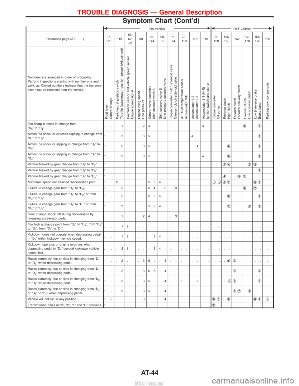
Numbers are arranged in order of probability.
Perform inspections starting with number one and
work up. Circled numbers indicate that the transmis-
sion must be removed from the vehicle.
Fluid level
Control linkage
Park/neutral position switch
Throttle (accelerator) position sensor (Adjustment)
Revolution sensor and vehicle speed sensor
Engine speed signal
Engine idling speed
Line pressure
Control valve assembly
Shift solenoid valve A
Shift solenoid valve B
Line pressure solenoid valve
Torque converter clutch solenoid valve
Overrun clutch solenoid valve
A/T fluid temperature sensor
Accumulator N-D
Accumulator 1-2
Accumulator 2-3
Accumulator 3-4 (N-R)
Ignition switch and starter
Torque converter
Oil pump
Reverse clutch
High clutch
Forward clutch
Forward one-way clutch
Overrun clutch
Low one-way clutch
Low & reverse brake
Brake band
Parking pawl components
Too sharp a shock in change from
ªD3ºtoªD4º. . ..1...24.........3. .
.....q6..q5.
Almost no shock or clutches slipping in change from
ªD
1ºtoªD2º. 1 ..2...35.......4... .
........q6.
Almost no shock or slipping in change from ªD
2ºto
ªD3º. 1 ..2...35........4.. ...
q6.....q7.
Almost no shock or slipping in change from ªD
3ºto
ªD4º. 1 ..2...35.........4. ...
q6.....q7.
Vehicle braked by gear change from ªD
1ºtoªD2º. 1 ................... .. q2q4...q5q3..
Vehicle braked by gear change from ªD
2ºtoªD3º. 1 ................... . ........q2.
Vehicle braked by gear change from ªD
3ºtoªD4º. 1 ................... .. q4..q3q2... .
Maximum speed not attained. Acceleration poor. 1 . 2 .....534.........q
11q10q6q7....q9q8.
Failure to change gear from ªD
4ºtoªD3º. 1 ..2....64.5.3...... . .....q8.q7..
Failure to change gear from ªD
3ºtoªD2º or from
ªD4ºtoªD2º. 1 ..2....534......... ...
q6.....q7.
Failure to change gear from ªD
2ºtoªD1º or from
ªD3ºtoªD1º. 1 ..2....534......... ...
q7...q6.q8.
Gear change shock felt during deceleration by
releasing accelerator pedal. . ..1...24....3...... .
......... .
Too high a change point from ªD
4ºtoªD3º, from ªD3º
to ªD2º, from ªD2ºtoªD1º. . ..12............... .
......... .
Kickdown does not operate when depressing pedal
in ªD
4º within kickdown vehicle speed. . ..12....34......... .
......... .
Kickdown operates or engine overruns when
depressing pedal in ªD
4º beyond kickdown vehicle
speed limit. . ..21....34......... .
......... .
Races extremely fast or slips in changing from ªD
4º
to ªD3º when depressing pedal. 1 ..2...35..4........ ...
q6q7..... .
Races extremely fast or slips in changing from ªD
4º
to ªD2º when depressing pedal. 1 ..2...365.4........ ....
q8....q7.
Races extremely fast or slips in changing from ªD
3º
to ªD2º when depressing pedal. 1 ..2...35..4..6..7.. ...
q10q9....q8.
Races extremely fast or slips in changing from ªD
4º
or ªD3ºtoªD1º when depressing pedal. 1 ..2...35..4........ ....
q6q7.q8.. .
Vehicle will not run in any position. 1 2 .....3...4........ q
9q5.q6.... q8q7q10
Transmission noise in ªDº, ª2º, ª1º and ªRº positions. 1
................... q2......... .
TROUBLE DIAGNOSIS Ð General Description
Symptom Chart (Cont'd)
AT-44
http://vnx.su/
Page 858 of 1833
FON vehicleEFOFF vehicleE
Reference page (AT- )27,
120 11 9 56,
62,
82 30
65,
144 68,
86 71,
74 78,
11 8 11 8 11 8 144,
128 156,
160 162162,
170 166,
176 180
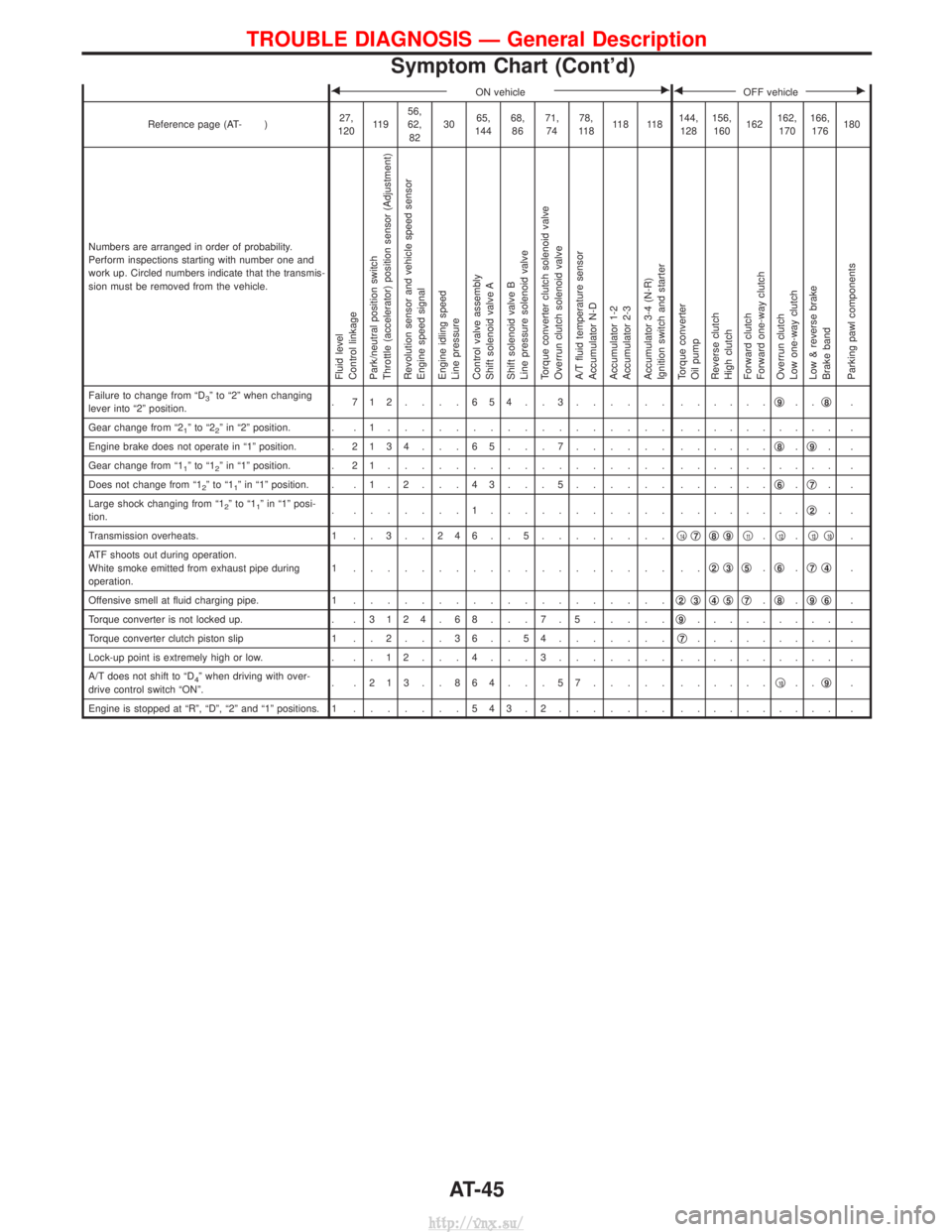
Numbers are arranged in order of probability.
Perform inspections starting with number one and
work up. Circled numbers indicate that the transmis-
sion must be removed from the vehicle.
Fluid level
Control linkage
Park/neutral position switch
Throttle (accelerator) position sensor (Adjustment)
Revolution sensor and vehicle speed sensor
Engine speed signal
Engine idling speed
Line pressure
Control valve assembly
Shift solenoid valve A
Shift solenoid valve B
Line pressure solenoid valve
Torque converter clutch solenoid valve
Overrun clutch solenoid valve
A/T fluid temperature sensor
Accumulator N-D
Accumulator 1-2
Accumulator 2-3
Accumulator 3-4 (N-R)
Ignition switch and starter
Torque converter
Oil pump
Reverse clutch
High clutch
Forward clutch
Forward one-way clutch
Overrun clutch
Low one-way clutch
Low & reverse brake
Brake band
Parking pawl components
Failure to change from ªD3º to ª2º when changing
lever into ª2º position. . 712....654..3...... .
.....q9..q8.
Gear change from ª2
1ºtoª22º in ª2º position. . . 1 ................. . ......... .
Engine brake does not operate in ª1º position. . 2134 . . . 65 . . . 7...... ......q
8.q9..
Gear change from ª1
1ºtoª12º in ª1º position. . 2 1 ................. . ......... .
Does not change from ª1
2ºtoª11º in ª1º position. . . 1 . 2 . . . 4 3 . . . 5 ...... ......q6.q7..
Large shock changing from ª1
2ºtoª11º in ª1º posi-
tion. . .......1........... .
.......q2..
Transmission overheats. 1 . . 3 . . 2 4 6 . . 5 ........q
14q7q8q9q11.q12.q13q10.
ATF shoots out during operation.
White smoke emitted from exhaust pipe during
operation. 1 ................... ..
q
2q3q5.q6.q7q4.
Offensive smell at fluid charging pipe. 1 ................... q
2q3q4q5q7.q8.q9q6.
Torque converter is not locked up. . . 3124 . 68 . . . 7 . 5.....q
9......... .
Torque converter clutch piston slip 1 . . 2 . . . 3 6 . . 5 4 .......q
7......... .
Lock-up point is extremely high or low. . . . 1 2 . . . 4 . . . 3 ....... .......... .
A/T does not shift to ªD
4º when driving with over-
drive control switch ªONº. . .213..864...57..... .
.....q10..q9.
Engine is stopped at ªRº, ªDº, ª2º and ª1º positions. 1 .......543.2....... . ......... .
TROUBLE DIAGNOSIS Ð General Description
Symptom Chart (Cont'd)
AT-45
http://vnx.su/
Page 1083 of 1833
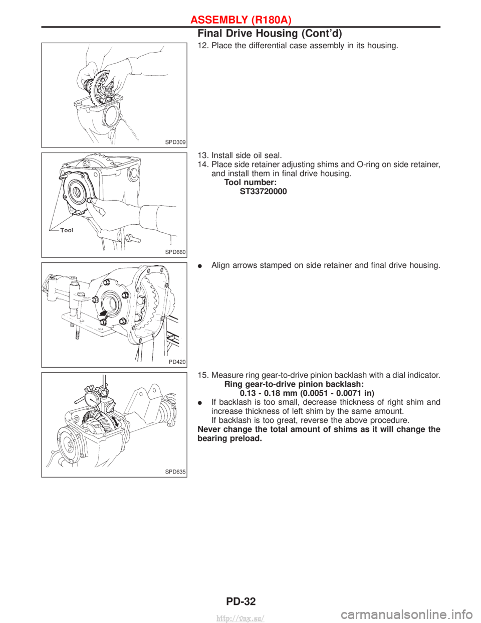
12. Place the differential case assembly in its housing.
13. Install side oil seal.
14. Place side retainer adjusting shims and O-ring on side retainer,and install them in final drive housing.Tool number: ST33720000
I Align arrows stamped on side retainer and final drive housing.
15. Measure ring gear-to-drive pinion backlash with a dial indicator. Ring gear-to-drive pinion backlash:0.13 - 0.18 mm (0.0051 - 0.0071 in)
I If backlash is too small, decrease thickness of right shim and
increase thickness of left shim by the same amount.
If backlash is too great, reverse the above procedure.
Never change the total amount of shims as it will change the
bearing preload.
SPD309
SPD660
PD420
SPD635
ASSEMBLY (R180A)
Final Drive Housing (Cont'd)
PD-32
http://vnx.su/
Page 1409 of 1833
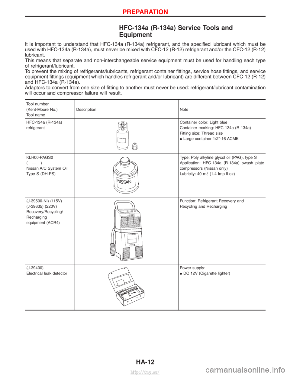
HFC-134a (R-134a) Service Tools and
Equipment
It is important to understand that HFC-134a (R-134a) refrigerant, and the specified lubricant which must be
used with HFC-134a (R-134a), must never be mixed with CFC-12 (R-12) refrigerant and/or the CFC-12 (R-12)
lubricant.
This means that separate and non-interchangeable service equipment must be used for handling each type
of refrigerant/lubricant.
To prevent the mixing of refrigerants/lubricants, refrigerant container fittings, service hose fittings, and service
equipment fittings (equipment which handles refrigerant and/or lubricant) are different between CFC-12 (R-12)
and HFC-134a (R-134a).
Adaptors to convert from one size of fitting to another must never be used: refrigerant/lubricant contamination
will occur and compressor failure will result.
Tool number
(Kent-Moore No.)
Tool nameDescription Note
HFC-134a (R-134a)
refrigerant
Container color: Light blue
Container marking: HFC-134a (R-134a)
Fitting size: Thread size
I Large container 1/2² -16 ACME
KLH00-PAGS0
(Ð)
Nissan A/C System Oil
Type S (DH-PS)
Type: Poly alkyline glycol oil (PAG), type S
Application: HFC-134a (R-134a) swash plate
compressors (Nissan only)
Lubricity: 40 m (1.4 Imp fl oz)
(J-39500-NI) (115V)
(J-39635) (220V)
Recovery/Recycling/
Recharging
equipment (ACR4)
Function: Refrigerant Recovery and
Recycling and Recharging
(J-39400)
Electrical leak detector
Power supply:
I DC 12V (Cigarette lighter)
PREPARATION
HA-12
http://vnx.su/
Page 1420 of 1833
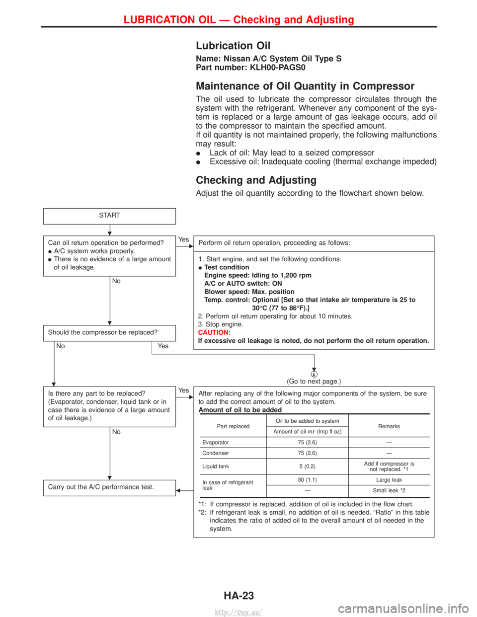
Lubrication Oil
Name: Nissan A/C System Oil Type S
Part number: KLH00-PAGS0
Maintenance of Oil Quantity in Compressor
The oil used to lubricate the compressor circulates through the
system with the refrigerant. Whenever any component of the sys-
tem is replaced or a large amount of gas leakage occurs, add oil
to the compressor to maintain the specified amount.
If oil quantity is not maintained properly, the following malfunctions
may result:
ILack of oil: May lead to a seized compressor
I Excessive oil: Inadequate cooling (thermal exchange impeded)
Checking and Adjusting
Adjust the oil quantity according to the flowchart shown below.
START
Can oil return operation be performed?
IA/C system works properly.
I There is no evidence of a large amount
of oil leakage.
No
EYe s
Perform oil return operation, proceeding as follows:
------------------------------------------------------------------------------------------------------------------------------------------------------------------------------------------------------------------------------------------------------------------------------------------------------------------------------------------------------------------------------------------------------------------------------------------------------------------------------------------------------------------------------------------------------------- 1. Start engine, and set the following conditions:
I Test condition
Engine speed: Idling to 1,200 rpm
A/C or AUTO switch: ON
Blower speed: Max. position
Temp. control: Optional [Set so that intake air temperature is 25 to
30ÉC (77 to 86ÉF).]
2. Perform oil return operating for about 10 minutes.
3. Stop engine.
CAUTION:
If excessive oil leakage is noted, do not perform the oil return operation.
Should the compressor be replaced?
No Yes
qA(Go to next page.)
Is there any part to be replaced?
(Evaporator, condenser, liquid tank or in
case there is evidence of a large amount
of oil leakage.)
No
EYe s After replacing any of the following major components of the system, be sure
to add the correct amount of oil to the system.
Amount of oil to be added
*1: If compressor is replaced, addition of oil is included in the flow chart.
*2: If refrigerant leak is small, no addition of oil is needed. ªRatioº in this table indicates the ratio of added oil to the overall amount of oil needed in the
system.
Carry out the A/C performance test.F
Part replaced Oil to be added to system
Remarks
Amount of oil m (Imp fl oz)
Evaporator 75 (2.6)Ð
Condenser 75 (2.6)Ð
Liquid tank 5 (0.2)Add if compressor is
not replaced. *1
In case of refrigerant
leak 30 (1.1)
Large leak
Ð Small leak *2
H
H
H
H
H
LUBRICATION OIL Ð Checking and Adjusting
HA-23
http://vnx.su/
Page 1431 of 1833
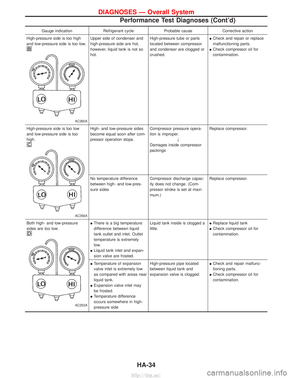
Gauge indicationRefrigerant cycleProbable causeCorrective action
High-pressure side is too high
and low-pressure side is too low.
AC360A
Upper side of condenser and
high-pressure side are hot,
however, liquid tank is not so
hot. High-pressure tube or parts
located between compressor
and condenser are clogged or
crushed.I
Check and repair or replace
malfunctioning parts.
I Check compressor oil for
contamination.
High-pressure side is too low
and low-pressure side is too
high.
AC356A
High- and low-pressure sides
become equal soon after com-
pressor operation stops. Compressor pressure opera-
tion is improper.
"
Damages inside compressor
packings Replace compressor.
No temperature difference
between high- and low-pres-
sure sides Compressor discharge capac-
ity does not change. (Com-
pressor stroke is set at maxi-
mum.)Replace compressor.
Both high- and low-pressure
sides are too low.
AC353A
I There is a big temperature
difference between liquid
tank outlet and inlet. Outlet
temperature is extremely
low.
I Liquid tank inlet and expan-
sion valve are frosted. Liquid tank inside is clogged a
little.
I
Replace liquid tank
I Check compressor oil for
contamination.
I Temperature of expansion
valve inlet is extremely low
as compared with areas near
liquid tank.
I Expansion valve inlet may
be frosted.
I Temperature difference
occurs somewhere in high-
pressure side High-pressure pipe located
between liquid tank and
expansion valve is clogged.
I
Check and repair malfunc-
tioning parts.
I Check compressor oil for
contamination.
DIAGNOSES Ð Overall System
Performance Test Diagnoses (Cont'd)
HA-34
http://vnx.su/
Page 1432 of 1833
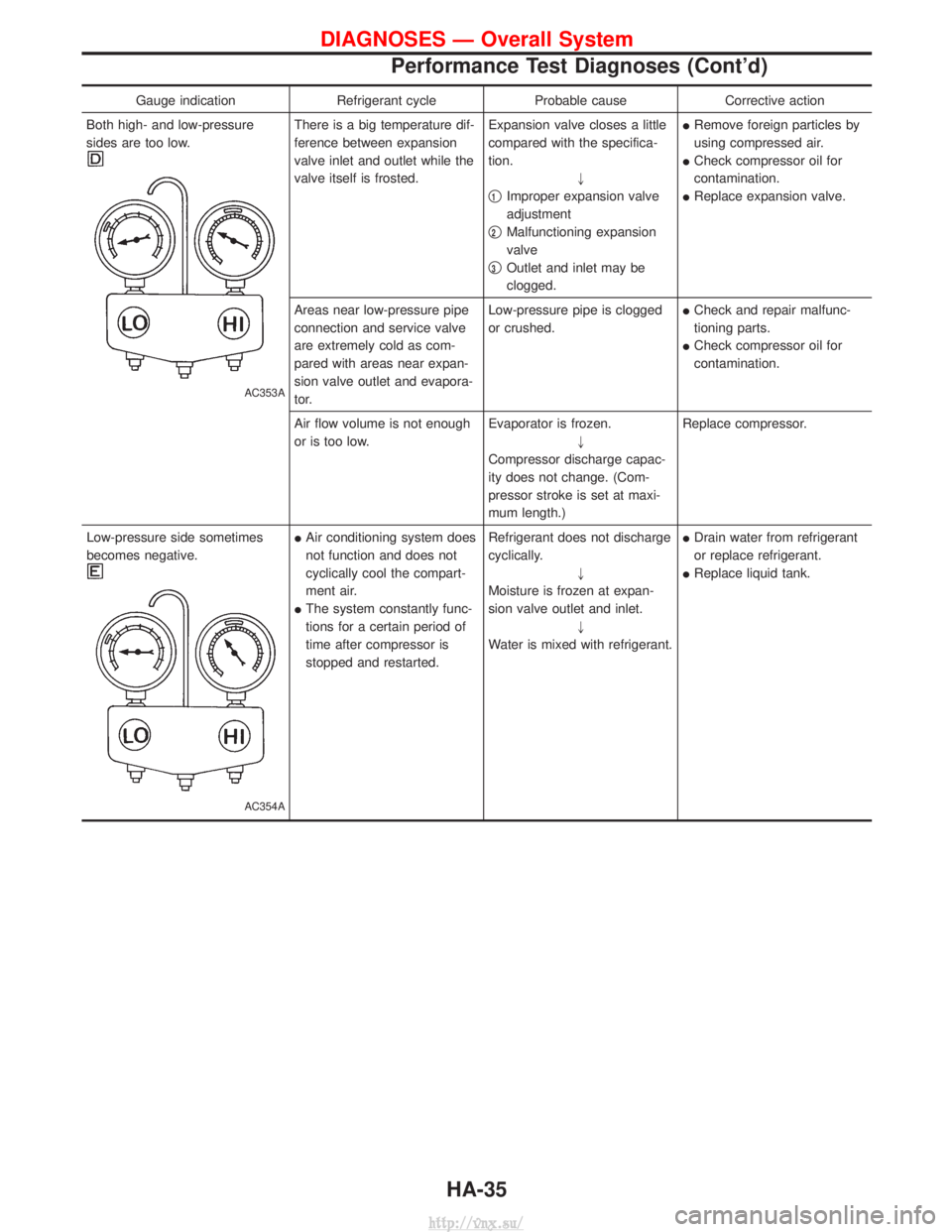
Gauge indicationRefrigerant cycleProbable causeCorrective action
Both high- and low-pressure
sides are too low.
AC353A
There is a big temperature dif-
ference between expansion
valve inlet and outlet while the
valve itself is frosted. Expansion valve closes a little
compared with the specifica-
tion.
"
q
1Improper expansion valve
adjustment
q
2Malfunctioning expansion
valve
q
3Outlet and inlet may be
clogged. I
Remove foreign particles by
using compressed air.
I Check compressor oil for
contamination.
I Replace expansion valve.
Areas near low-pressure pipe
connection and service valve
are extremely cold as com-
pared with areas near expan-
sion valve outlet and evapora-
tor. Low-pressure pipe is clogged
or crushed.
I
Check and repair malfunc-
tioning parts.
I Check compressor oil for
contamination.
Air flow volume is not enough
or is too low. Evaporator is frozen.
"
Compressor discharge capac-
ity does not change. (Com-
pressor stroke is set at maxi-
mum length.) Replace compressor.
Low-pressure side sometimes
becomes negative.
AC354A
I Air conditioning system does
not function and does not
cyclically cool the compart-
ment air.
I The system constantly func-
tions for a certain period of
time after compressor is
stopped and restarted. Refrigerant does not discharge
cyclically.
"
Moisture is frozen at expan-
sion valve outlet and inlet. "
Water is mixed with refrigerant. I
Drain water from refrigerant
or replace refrigerant.
I Replace liquid tank.
DIAGNOSES Ð Overall System
Performance Test Diagnoses (Cont'd)
HA-35
http://vnx.su/