Page 512 of 1833

Description
SYSTEM DESCRIPTION
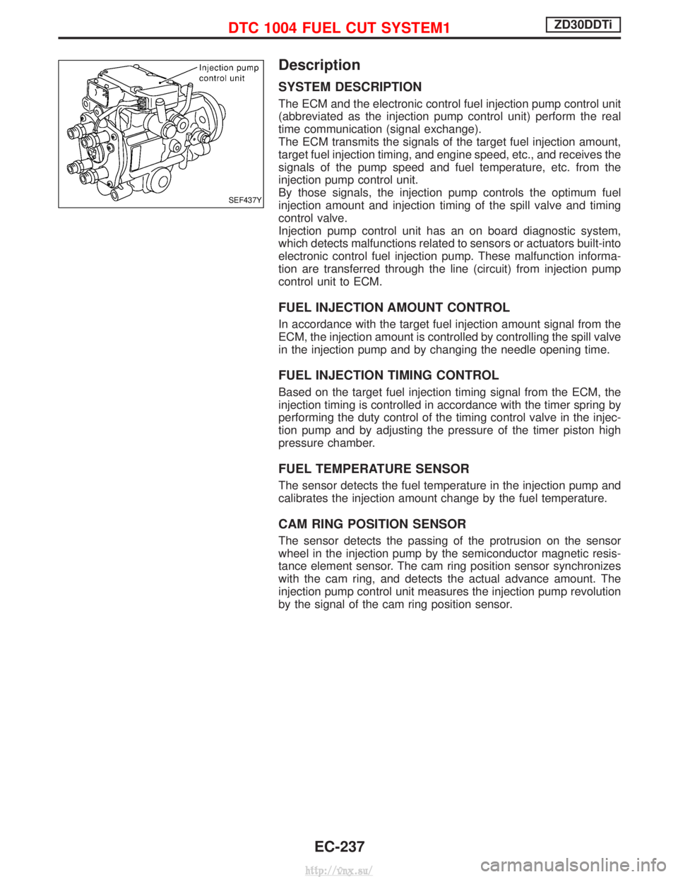
The ECM and the electronic control fuel injection pump control unit
(abbreviated as the injection pump control unit) perform the real
time communication (signal exchange).
The ECM transmits the signals of the target fuel injection amount,
target fuel injection timing, and engine speed, etc., and receives the
signals of the pump speed and fuel temperature, etc. from the
injection pump control unit.
By those signals, the injection pump controls the optimum fuel
injection amount and injection timing of the spill valve and timing
control valve.
Injection pump control unit has an on board diagnostic system,
which detects malfunctions related to sensors or actuators built-into
electronic control fuel injection pump. These malfunction informa-
tion are transferred through the line (circuit) from injection pump
control unit to ECM.
FUEL INJECTION AMOUNT CONTROL
In accordance with the target fuel injection amount signal from the
ECM, the injection amount is controlled by controlling the spill valve
in the injection pump and by changing the needle opening time.
FUEL INJECTION TIMING CONTROL
Based on the target fuel injection timing signal from the ECM, the
injection timing is controlled in accordance with the timer spring by
performing the duty control of the timing control valve in the injec-
tion pump and by adjusting the pressure of the timer piston high
pressure chamber.
FUEL TEMPERATURE SENSOR
The sensor detects the fuel temperature in the injection pump and
calibrates the injection amount change by the fuel temperature.
CAM RING POSITION SENSOR
The sensor detects the passing of the protrusion on the sensor
wheel in the injection pump by the semiconductor magnetic resis-
tance element sensor. The cam ring position sensor synchronizes
with the cam ring, and detects the actual advance amount. The
injection pump control unit measures the injection pump revolution
by the signal of the cam ring position sensor.
SEF437Y
DTC 1004 FUEL CUT SYSTEM1ZD30DDTi
EC-237
http://vnx.su/
Page 1121 of 1833
[Example]
(Measures taken at one side):
(1)
Angle
Specified value Measured Change
Camber angle 0É30¢ 0É5¢+0É25¢
Caster angle 1É54¢ 2É10¢þ0É16¢
The above values relate to the graph below:
Shim thickness selection graph
(2) Obtain intersection point of lines in accordance with the graph.
Front: 1.4 mm
Rear: 2.0 mm
(3) Choose shims which are nearest to the values found in the graph:Front: 1.6 mm
Rear: 2.0 mm
(4) If shim thicknesses as calculated appear not to be available, combinations of different shims should be used to meet the
desired total thickness of the shims.
EFA015
CHECK AND ADJUSTMENT
Front Wheel Alignment (Cont'd)
FA-10
http://vnx.su/
Page 1201 of 1833
Shoe Replacement
When installing new shoes, springs should be changed as well.
Check lining thickness.Standard lining thickness:Trailing: 3.95 mm (0.156 in)
Leading: 8.95 mm (0.352 in)
Lining wear limit (A): 1.52 mm (0.0598 in)
Inspection
WHEEL CYLINDER
ICheck wheel cylinder for leakage.
I Check for wear, damage and loose conditions.
Replace if any such condition exists.
DRUM
Maximum inner diameter:
282 mm (11.10 in)
Out of roundness: 0.05 mm (0.019 in) or less
I Contact surface should be fine finished with No. 120 to 150
emery paper.
I If any scratches or wear are detected, adjust the alignment of
the drum.
I After brake drum has been completely reconditioned or
replaced, check drum and shoes for proper contact pattern.
Installation
Always perform shoe clearance adjustment. Refer to
ªAdjustmentº, ªPARKING BRAKE CONTROLº, BR-36.
1. Fit adjuster assembly.
SBR021A
SBR018C
SBR019C
EBR089
REAR DRUM BRAKE
BR-34
http://vnx.su/
Page 1399 of 1833

Supplemental Restraint System (SRS) ªAIR
BAGº and ªSEAT BELT PRE-TENSIONERº
The Supplemental Restraint System such as ªAIR BAGº and ªSEAT BELT PRE-TENSIONERº used along with
a seat belt, helps to reduce the risk or severity of injury to the driver and front passenger for certain types of
collision. The SRS composition which is available to NISSAN MODEL R20 is as follows (The composition
varies according to the destination and optional equipment.):
IFor a frontal collision
The Supplemental Restraint System consists of driver air bag module (located in the center of the steer-
ing wheel), front passenger air bag module (located on the instrument panel on passenger side), front seat
belt pre-tensioners, a diagnosis sensor unit, warning lamp, wiring harness and spiral cable.
I For a side collision
The Supplemental Restraint System consists of front side air bag module (located in the outer side of front
seat), side air bag (satellite) sensor, diagnosis sensor unit (one of components of air bags for a frontal
collision), wiring harness, warning lamp (one of components of air bags for a frontal collision).
WARNING:
I To avoid rendering the SRS inoperative, which could increase the risk of personal injury or death
in the event of a collision which would result in air bag inflation, all maintenance should be per-
formed by an authorized NISSAN dealer.
I Improper maintenance, including incorrect removal and installation of the SRS, can lead to per-
sonal injury caused by unintentional activation of the system.
I Do not use electrical test equipment on any circuit related to the SRS unless instructed to in this
Service Manual. Spiral cable and wiring harnesses covered with yellow insulation tape either just
before the harness connectors or for the complete harness are related to the SRS.
Introduction
To prevent the ozone layer from being destroyed, the HFC-134a (R-134a) refrigerant has replaced the previ-
ously used CFC-12 (R-12).
The new and previous service tools, refrigerant, lubricant, etc. are not interchangeable due to differences in
their physical properties and characteristics.
Always service the HFC-134a (R-134a) air conditioning system using the specified tools, lubricant and
refrigerant, observing the following precautions:
PRECAUTIONS
HA-2
http://vnx.su/