Page 1158 of 1833
Removal
IDisconnect parking brake cable and brake tube.
I Remove nuts securing wheel bearing cage with baffle plate.
I Remove ABS sensor.
I Draw out axle shaft with Tool.
When drawing out axle shaft, be careful not to damage oil seal.
I Remove oil seal.
Do not reuse oil seal one it is removed.
Always install new one.
I Remove ABS-rotor using special tool.
I Unbend lock washer with a screwdriver.
Do not reuse lock washer once it is removed.
Always install new one.
ERA013
NRA025
YRA004
NRA024
SRA104
REAR AXLE
RA-7
http://vnx.su/
Page 1161 of 1833
ISecure lock nut by bending one portion of lock washer.
Installation
Install the sensor rotor using suitable drift and press.
IAlways replace sensor rotor with new one.
I Pay attention to the direction of front sensor rotor as shown in
figure.
I Install new oil seal to rear axle housing using a suitable tool.
After installing new oil seal, coat sealing lip with multi-purpose
grease.
I Position axle shafts in rear axle housing.
Be careful not to damage oil seal.
I When the ball-bearing holder and the brake are installed in the
base of the axle, they need to be correctly positioned.
A quick way to determine on which side the holder should be
located, is to look at the brake adjustment screw. Left-hand thread:Install the holder on the left side.
Right-hand thread (Normal) Install the holder on the right side.
SRA104
SBR402D
SRA292A
ERA017
REAR AXLE
Installation (Cont'd)
RA-10
http://vnx.su/
Page 1176 of 1833
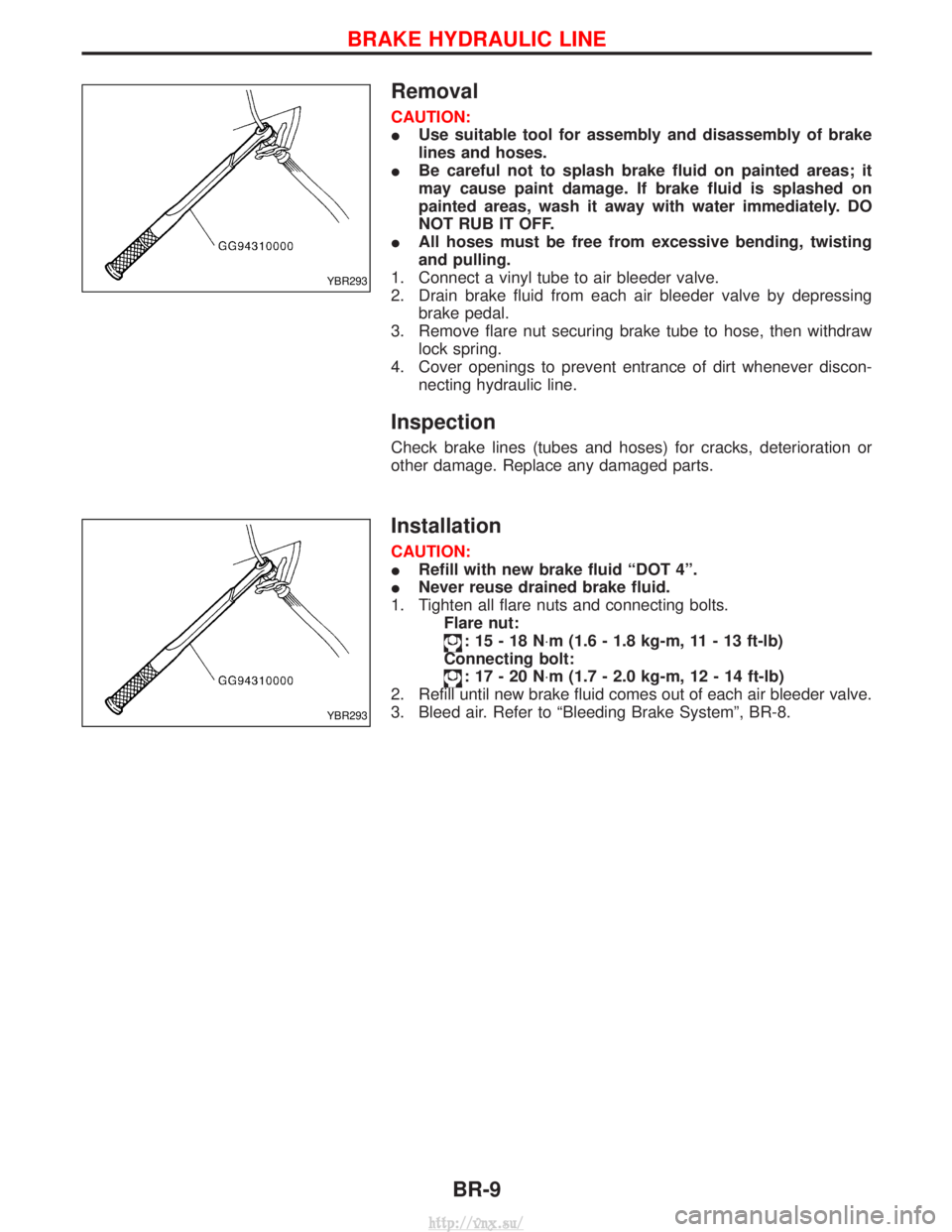
Removal
CAUTION:
IUse suitable tool for assembly and disassembly of brake
lines and hoses.
I Be careful not to splash brake fluid on painted areas; it
may cause paint damage. If brake fluid is splashed on
painted areas, wash it away with water immediately. DO
NOT RUB IT OFF.
I All hoses must be free from excessive bending, twisting
and pulling.
1. Connect a vinyl tube to air bleeder valve.
2. Drain brake fluid from each air bleeder valve by depressing brake pedal.
3. Remove flare nut securing brake tube to hose, then withdraw lock spring.
4. Cover openings to prevent entrance of dirt whenever discon- necting hydraulic line.
Inspection
Check brake lines (tubes and hoses) for cracks, deterioration or
other damage. Replace any damaged parts.
Installation
CAUTION:
IRefill with new brake fluid ªDOT 4º.
I Never reuse drained brake fluid.
1. Tighten all flare nuts and connecting bolts. Flare nut:
:15-18N ×m (1.6 - 1.8 kg-m, 11 - 13 ft-lb)
Connecting bolt:
:17-20N ×m (1.7 - 2.0 kg-m, 12 - 14 ft-lb)
2. Refill until new brake fluid comes out of each air bleeder valve.
3. Bleed air. Refer to ªBleeding Brake Systemº, BR-8.
YBR293
YBR293
BRAKE HYDRAULIC LINE
BR-9
http://vnx.su/
Page 1182 of 1833
Removal
1. Remove stop lamp switch connector and stop lamp switch.
2. Remove bolt for (LHD) or nut for (RHD) securing pedal bracketto the front panel.
3. Remove snap ring and pull clevis pin from the brake pedal.
4. Remove 4 mounting nuts securing pedal bracket to the brake booster.
Installation
Install pedal bracket in the reverse order of the removal.
NOTE:
Pay attention to the direction of the clevis pin for installation.
Inspection
Check brake pedal for following items:
IBrake pedal bend
I Clevis pin deformation
I Crack of any welded portion
I Crack or deformation of clevis pin stopper
SBR997
BRAKE PEDAL AND BRACKET
BR-15
http://vnx.su/
Page 1184 of 1833
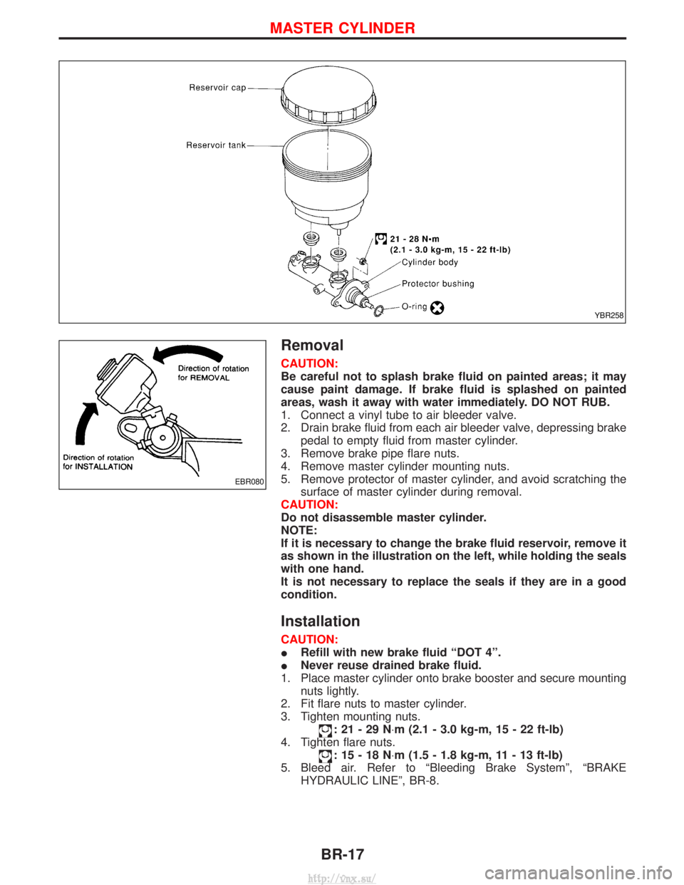
Removal
CAUTION:
Be careful not to splash brake fluid on painted areas; it may
cause paint damage. If brake fluid is splashed on painted
areas, wash it away with water immediately. DO NOT RUB.
1. Connect a vinyl tube to air bleeder valve.
2. Drain brake fluid from each air bleeder valve, depressing brakepedal to empty fluid from master cylinder.
3. Remove brake pipe flare nuts.
4. Remove master cylinder mounting nuts.
5. Remove protector of master cylinder, and avoid scratching the surface of master cylinder during removal.
CAUTION:
Do not disassemble master cylinder.
NOTE:
If it is necessary to change the brake fluid reservoir, remove it
as shown in the illustration on the left, while holding the seals
with one hand.
It is not necessary to replace the seals if they are in a good
condition.
Installation
CAUTION:
I Refill with new brake fluid ªDOT 4º.
I Never reuse drained brake fluid.
1. Place master cylinder onto brake booster and secure mounting nuts lightly.
2. Fit flare nuts to master cylinder.
3. Tighten mounting nuts.
:21-29N ×m (2.1 - 3.0 kg-m, 15 - 22 ft-lb)
4. Tighten flare nuts.
:15-18N ×m (1.5 - 1.8 kg-m, 11 - 13 ft-lb)
5. Bleed air. Refer to ªBleeding Brake Systemº, ªBRAKE HYDRAULIC LINEº, BR-8.
YBR258
EBR080
MASTER CYLINDER
BR-17
http://vnx.su/
Page 1186 of 1833
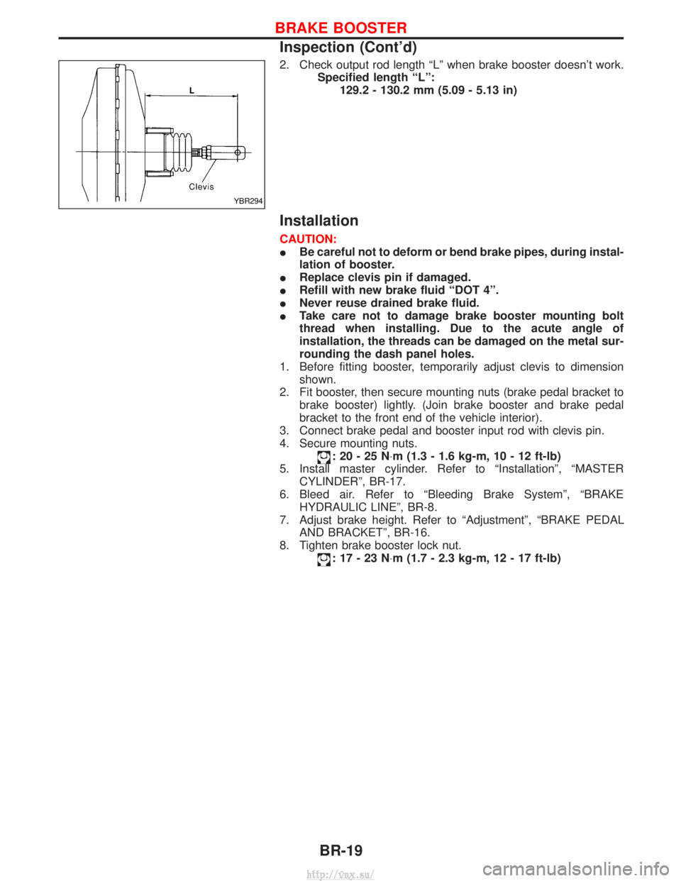
2. Check output rod length ªLº when brake booster doesn't work.Specified length ªLº:129.2 - 130.2 mm (5.09 - 5.13 in)
Installation
CAUTION:
IBe careful not to deform or bend brake pipes, during instal-
lation of booster.
I Replace clevis pin if damaged.
I Refill with new brake fluid ªDOT 4º.
I Never reuse drained brake fluid.
I Take care not to damage brake booster mounting bolt
thread when installing. Due to the acute angle of
installation, the threads can be damaged on the metal sur-
rounding the dash panel holes.
1. Before fitting booster, temporarily adjust clevis to dimension shown.
2. Fit booster, then secure mounting nuts (brake pedal bracket to brake booster) lightly. (Join brake booster and brake pedal
bracket to the front end of the vehicle interior).
3. Connect brake pedal and booster input rod with clevis pin.
4. Secure mounting nuts.
:20-25N ×m (1.3 - 1.6 kg-m, 10 - 12 ft-lb)
5. Install master cylinder. Refer to ªInstallationº, ªMASTER CYLINDERº, BR-17.
6. Bleed air. Refer to ªBleeding Brake Systemº, ªBRAKE HYDRAULIC LINEº, BR-8.
7. Adjust brake height. Refer to ªAdjustmentº, ªBRAKE PEDAL AND BRACKETº, BR-16.
8. Tighten brake booster lock nut.
:17-23N ×m (1.7 - 2.3 kg-m, 12 - 17 ft-lb)
YBR294
BRAKE BOOSTER
Inspection (Cont'd)
BR-19
http://vnx.su/
Page 1196 of 1833
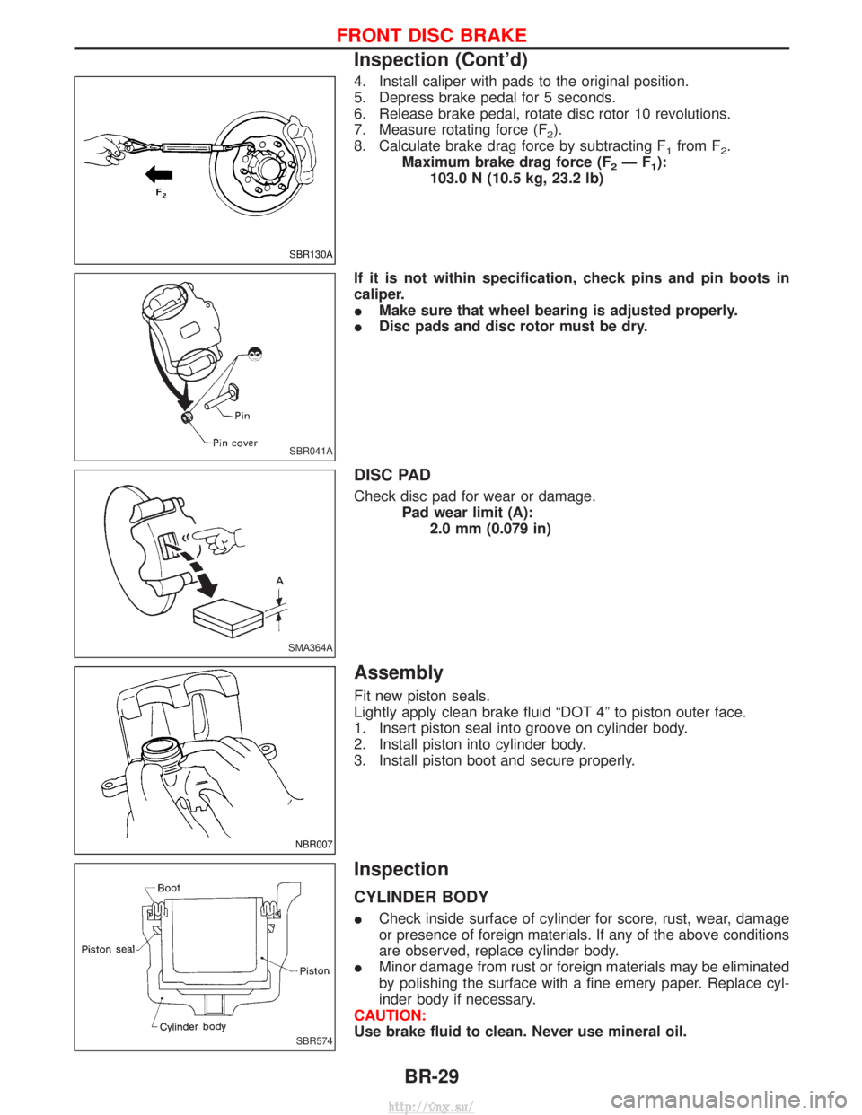
4. Install caliper with pads to the original position.
5. Depress brake pedal for 5 seconds.
6. Release brake pedal, rotate disc rotor 10 revolutions.
7. Measure rotating force (F
2).
8. Calculate brake drag force by subtracting F
1from F2.
Maximum brake drag force (F
2ÐF1):
103.0 N (10.5 kg, 23.2 lb)
If it is not within specification, check pins and pin boots in
caliper.
I Make sure that wheel bearing is adjusted properly.
I Disc pads and disc rotor must be dry.
DISC PAD
Check disc pad for wear or damage.
Pad wear limit (A):2.0 mm (0.079 in)
Assembly
Fit new piston seals.
Lightly apply clean brake fluid ªDOT 4º to piston outer face.
1. Insert piston seal into groove on cylinder body.
2. Install piston into cylinder body.
3. Install piston boot and secure properly.
Inspection
CYLINDER BODY
ICheck inside surface of cylinder for score, rust, wear, damage
or presence of foreign materials. If any of the above conditions
are observed, replace cylinder body.
I Minor damage from rust or foreign materials may be eliminated
by polishing the surface with a fine emery paper. Replace cyl-
inder body if necessary.
CAUTION:
Use brake fluid to clean. Never use mineral oil.
SBR130A
SBR041A
SMA364A
NBR007
SBR574
FRONT DISC BRAKE
Inspection (Cont'd)
BR-29
http://vnx.su/
Page 1197 of 1833
PISTON
Check outside surface of piston for score, rust, wear, damage or
presence of foreign materials. Replace if any of the above condi-
tions are observed.
CAUTION:
Piston sliding surface is plated. Do not polish with emery
paper even if rust or foreign materials are stuck to sliding
surface.
PIN, PIN BOLT AND PIN BOLT
Check for wear, cracks or other damage. Replace if any of the
above conditions are observed.
ROTOR
Rubbing surface
Check rotor for roughness, cracks or chips.
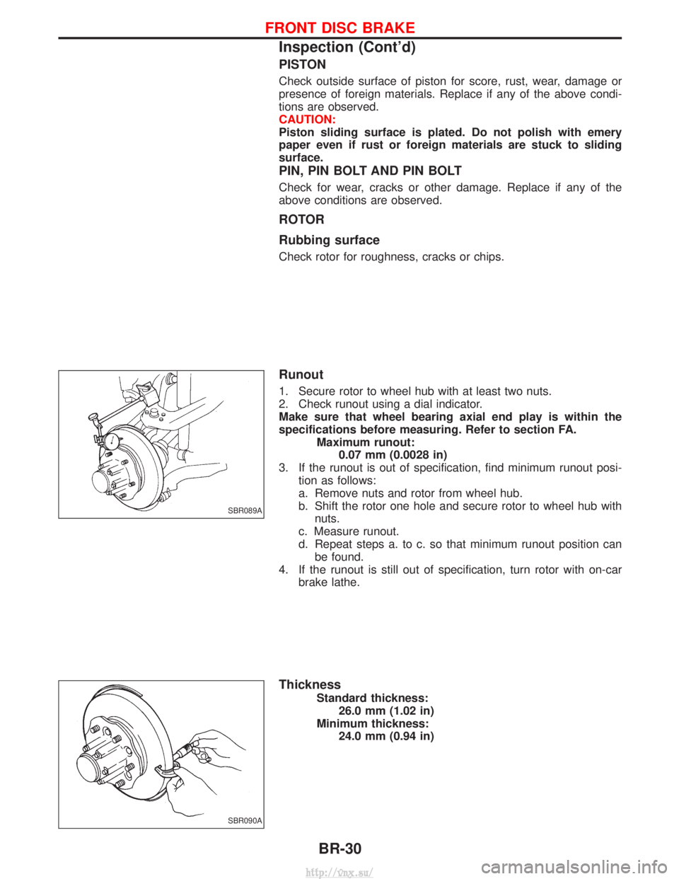
Runout
1. Secure rotor to wheel hub with at least two nuts.
2. Check runout using a dial indicator.
Make sure that wheel bearing axial end play is within the
specifications before measuring. Refer to section FA.Maximum runout:0.07 mm (0.0028 in)
3. If the runout is out of specification, find minimum runout posi- tion as follows:
a. Remove nuts and rotor from wheel hub.
b. Shift the rotor one hole and secure rotor to wheel hub withnuts.
c. Measure runout.
d. Repeat steps a. to c. so that minimum runout position can be found.
4. If the runout is still out of specification, turn rotor with on-car brake lathe.
Thickness
Standard thickness: 26.0 mm (1.02 in)
Minimum thickness: 24.0 mm (0.94 in)
SBR089A
SBR090A
FRONT DISC BRAKE
Inspection (Cont'd)
BR-30
http://vnx.su/