2004 NISSAN TERRANO ECU
[x] Cancel search: ECUPage 896 of 1833
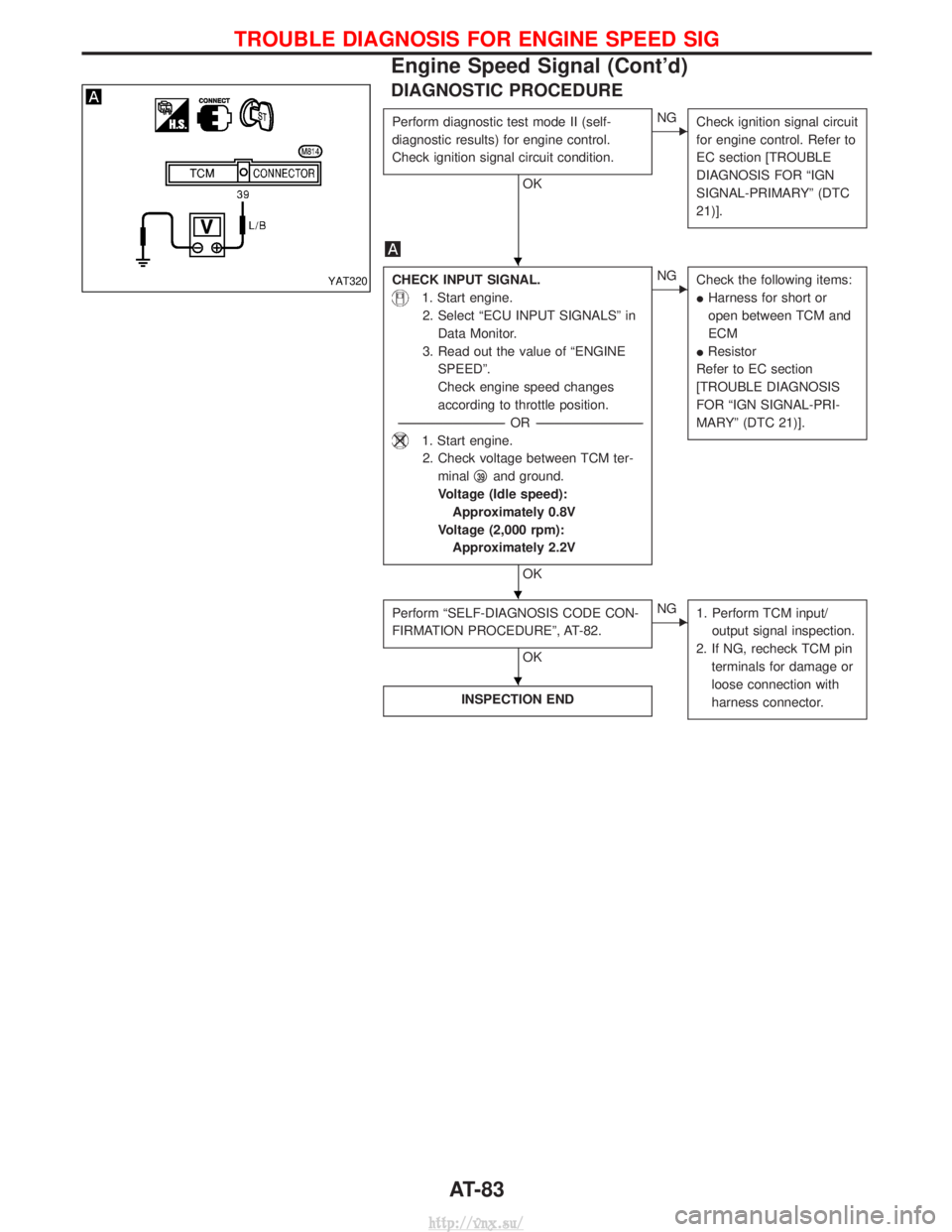
DIAGNOSTIC PROCEDURE
Perform diagnostic test mode II (self-
diagnostic results) for engine control.
Check ignition signal circuit condition.
OK
ENGCheck ignition signal circuit
for engine control. Refer to
EC section [TROUBLE
DIAGNOSIS FOR ªIGN
SIGNAL-PRIMARYº (DTC
21)].
CHECK INPUT SIGNAL.
1. Start engine.
2. Select ªECU INPUT SIGNALSº in Data Monitor.
3. Read out the value of ªENGINE SPEEDº.
Check engine speed changes
according to throttle position.
---------------------------------------------------------------------------------------------------------------------- -OR -----------------------------------------------------------------------------------------------------------------------
1. Start engine.
2. Check voltage between TCM ter- minal q
39and ground.
Voltage (Idle speed): Approximately 0.8V
Voltage (2,000 rpm): Approximately 2.2V
OK
ENG Check the following items:
IHarness for short or
open between TCM and
ECM
I Resistor
Refer to EC section
[TROUBLE DIAGNOSIS
FOR ªIGN SIGNAL-PRI-
MARYº (DTC 21)].
Perform ªSELF-DIAGNOSIS CODE CON-
FIRMATION PROCEDUREº, AT-82.
OK
ENG 1. Perform TCM input/
output signal inspection.
2. If NG, recheck TCM pin terminals for damage or
loose connection with
harness connector.
INSPECTION END
YAT320
H
H
H
TROUBLE DIAGNOSIS FOR ENGINE SPEED SIG
Engine Speed Signal (Cont'd)
AT-83
http://vnx.su/
Page 907 of 1833
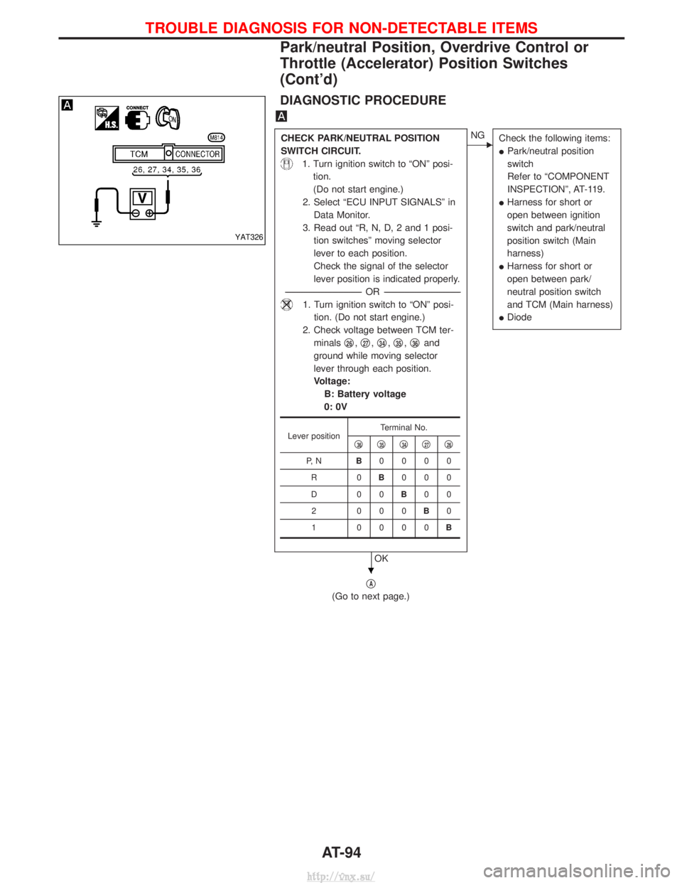
DIAGNOSTIC PROCEDURE
CHECK PARK/NEUTRAL POSITION
SWITCH CIRCUIT.
1. Turn ignition switch to ªONº posi-tion.
(Do not start engine.)
2. Select ªECU INPUT SIGNALSº in Data Monitor.
3. Read out ªR, N, D, 2 and 1 posi- tion switchesº moving selector
lever to each position.
Check the signal of the selector
lever position is indicated properly.
---------------------------------------------------------------------------------------------------------------------- -OR -----------------------------------------------------------------------------------------------------------------------
1. Turn ignition switch to ªONº posi-
tion. (Do not start engine.)
2. Check voltage between TCM ter- minals q
26,q27,q34,q35,q36and
ground while moving selector
lever through each position.
Voltage: B: Battery voltage
0: 0V
OK
ENG Check the following items:
IPark/neutral position
switch
Refer to ªCOMPONENT
INSPECTIONº, AT-119.
I Harness for short or
open between ignition
switch and park/neutral
position switch (Main
harness)
I Harness for short or
open between park/
neutral position switch
and TCM (Main harness)
I Diode
qA
(Go to next page.)
Lever position Terminal No.
q36q35q34q27q26
P, N B0000
R0 B000
D00 B00
2 000 B0
1 0000 B
YAT326
H
TROUBLE DIAGNOSIS FOR NON-DETECTABLE ITEMS
Park/neutral Position, Overdrive Control or
Throttle (Accelerator) Position Switches
(Cont'd)
AT-94
http://vnx.su/
Page 908 of 1833
qA
CHECK OVERDRIVE CONTROL
SWITCH CIRCUIT.
1. Turn ignition switch to ªONº posi-tion.
(Do not start engine.)
2. Select ªECU INPUT SIGNALSº in Data Monitor.
3. Read out ªOVERDRIVE SWITCHº. Check the signal of the overdrive
control switch is indicated prop-
erly.
(Overdrive control switch ªONº
displayed on CONSULT-II means
overdrive ªOFFº.)
---------------------------------------------------------------------------------------------------------------------- -OR -----------------------------------------------------------------------------------------------------------------------
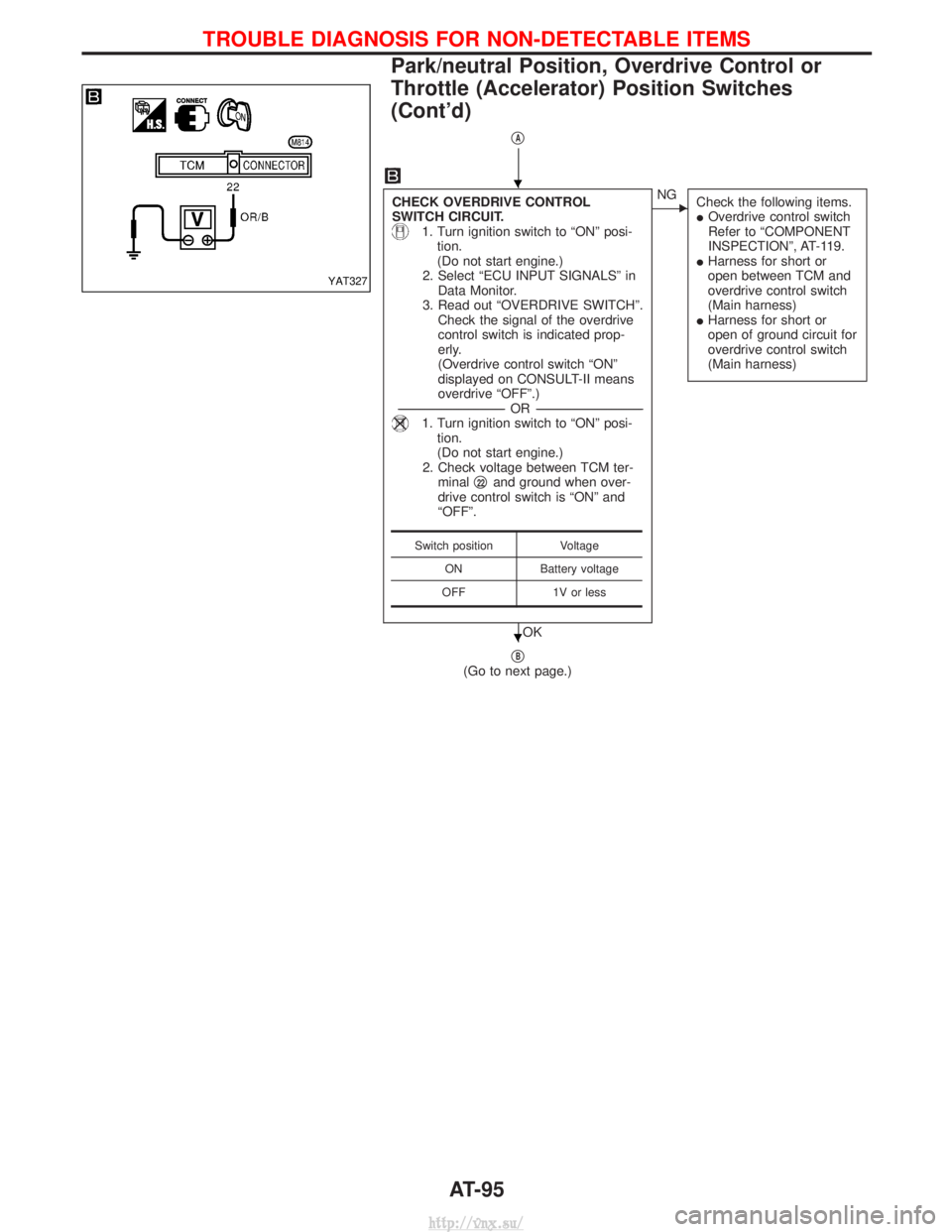
1. Turn ignition switch to ªONº posi-
tion.
(Do not start engine.)
2. Check voltage between TCM ter- minal q
22and ground when over-
drive control switch is ªONº and
ªOFFº.
OK
ENG Check the following items.
IOverdrive control switch
Refer to ªCOMPONENT
INSPECTIONº, AT-119.
I Harness for short or
open between TCM and
overdrive control switch
(Main harness)
I Harness for short or
open of ground circuit for
overdrive control switch
(Main harness)
qB(Go to next page.)
Switch position Voltage
ON Battery voltage
OFF 1V or less
YAT327
H
H
TROUBLE DIAGNOSIS FOR NON-DETECTABLE ITEMS
Park/neutral Position, Overdrive Control or
Throttle (Accelerator) Position Switches
(Cont'd)
AT-95
http://vnx.su/
Page 909 of 1833
qB
CHECK THROTTLE (ACCELERATOR)
POSITION SWITCH CIRCUIT.
1. Turn ignition switch to ªONº posi-tion.
(Do not start engine.)
2. Select ªECU INPUT SIGNALSº in Data Monitor.
3. Read out ªCLOSED THL/SWº and ªW/O THRL/P-SWº depressing
and releasing accelerator pedal.
Check the signal of throttle (accel-
erator) position switch is indicated
properly.
---------------------------------------------------------------------------------------------------------------------- -OR -----------------------------------------------------------------------------------------------------------------------
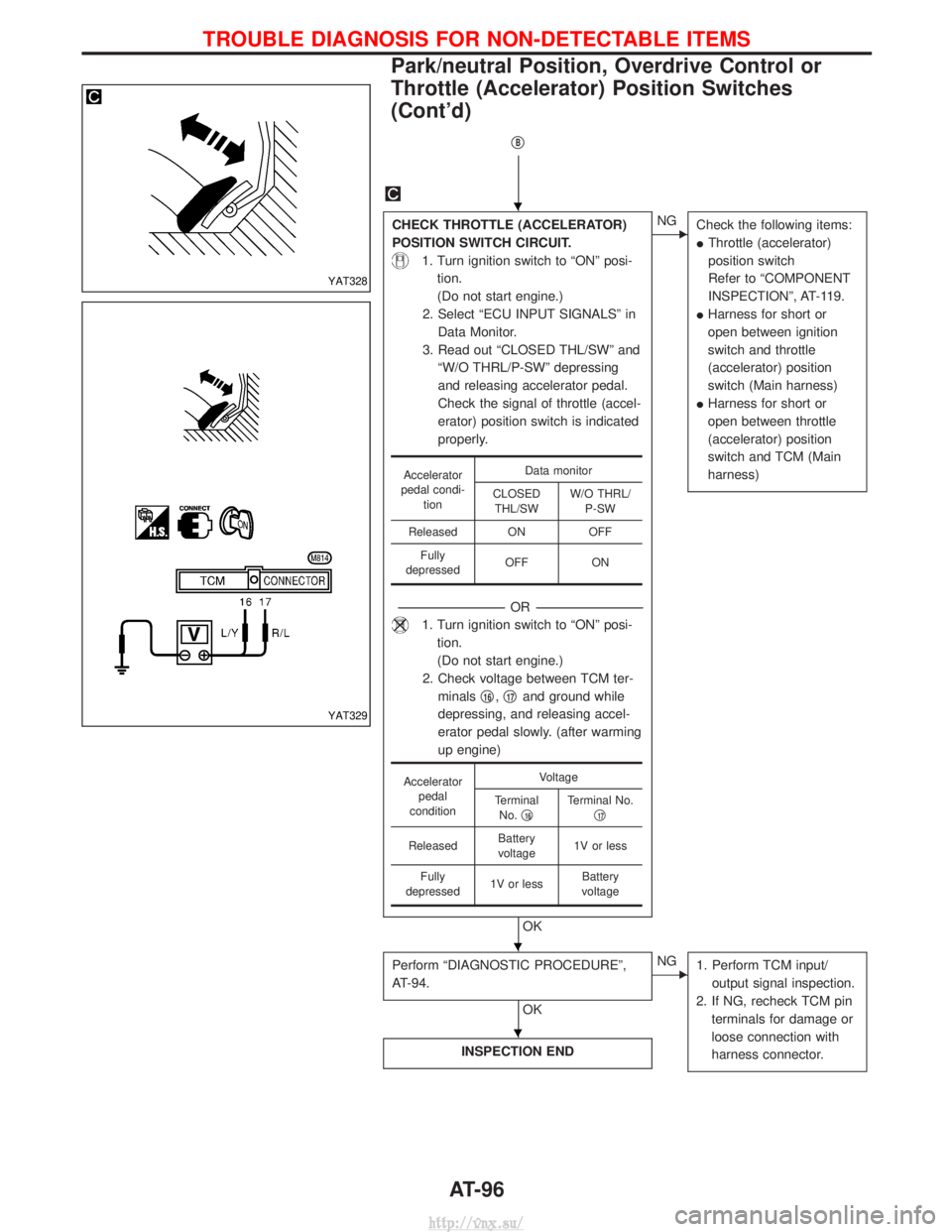
1. Turn ignition switch to ªONº posi-
tion.
(Do not start engine.)
2. Check voltage between TCM ter- minals q
16,q17and ground while
depressing, and releasing accel-
erator pedal slowly. (after warming
up engine)
OK
ENG Check the following items:
IThrottle (accelerator)
position switch
Refer to ªCOMPONENT
INSPECTIONº, AT-119.
I Harness for short or
open between ignition
switch and throttle
(accelerator) position
switch (Main harness)
I Harness for short or
open between throttle
(accelerator) position
switch and TCM (Main
harness)
Perform ªDIAGNOSTIC PROCEDUREº,
AT-94.
OK
ENG
1. Perform TCM input/
output signal inspection.
2. If NG, recheck TCM pin terminals for damage or
loose connection with
harness connector.
INSPECTION END
Accelerator
pedal condi- tion Data monitor
CLOSED THL/SW W/O THRL/
P-SW
Released ON OFF Fully
depressed OFF ON
Accelerator
pedal
condition Voltage
Terminal No. q
16Terminal No.
q17
Released Battery
voltage 1V or less
Fully
depressed 1V or less Battery
voltage
YAT328
YAT329
H
H
H
TROUBLE DIAGNOSIS FOR NON-DETECTABLE ITEMS
Park/neutral Position, Overdrive Control or
Throttle (Accelerator) Position Switches
(Cont'd)
AT-96
http://vnx.su/
Page 915 of 1833
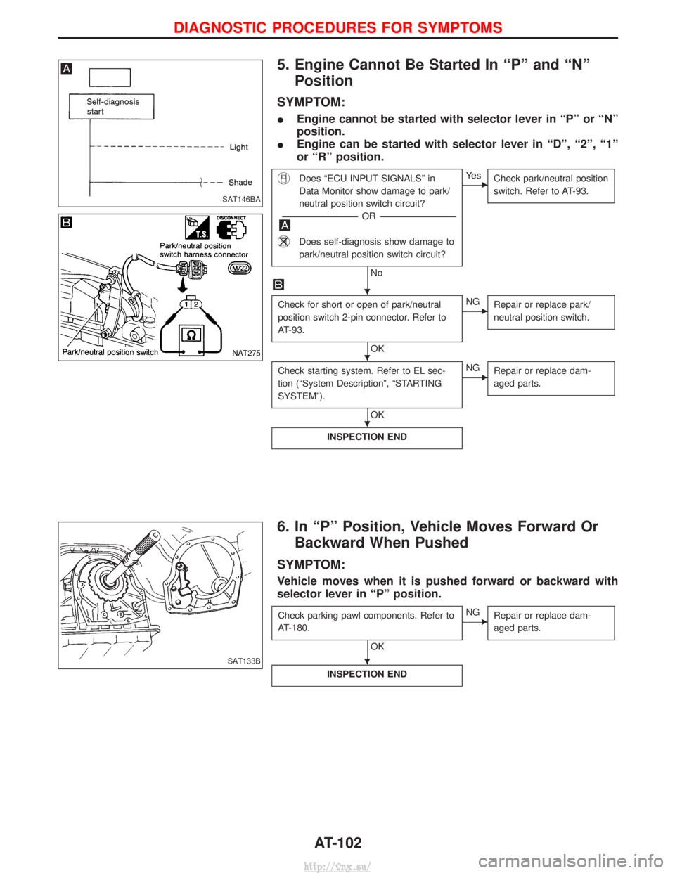
5. Engine Cannot Be Started In ªPº and ªNºPosition
SYMPTOM:
I Engine cannot be started with selector lever in ªPº or ªNº
position.
I Engine can be started with selector lever in ªDº, ª2º, ª1º
or ªRº position.
Does ªECU INPUT SIGNALSº in
Data Monitor show damage to park/
neutral position switch circuit?
---------------------------------------------------------------------------------------------------------------------- -OR -----------------------------------------------------------------------------------------------------------------------
Does self-diagnosis show damage to
park/neutral position switch circuit?
No
EYe s
Check park/neutral position
switch. Refer to AT-93.
Check for short or open of park/neutral
position switch 2-pin connector. Refer to
AT-93.
OK
ENGRepair or replace park/
neutral position switch.
Check starting system. Refer to EL sec-
tion (ªSystem Descriptionº, ªSTARTING
SYSTEMº).
OK
ENGRepair or replace dam-
aged parts.
INSPECTION END
6. In ªPº Position, Vehicle Moves Forward Or
Backward When Pushed
SYMPTOM:
Vehicle moves when it is pushed forward or backward with
selector lever in ªPº position.
Check parking pawl components. Refer to
AT-180.
OK
ENG Repair or replace dam-
aged parts.
INSPECTION END
SAT146BA
NAT275
SAT133B
H
H
H
H
DIAGNOSTIC PROCEDURES FOR SYMPTOMS
AT-102
http://vnx.su/
Page 916 of 1833
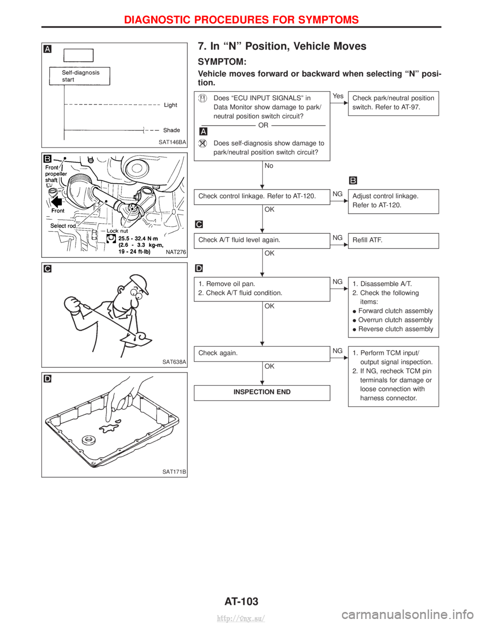
7. In ªNº Position, Vehicle Moves
SYMPTOM:
Vehicle moves forward or backward when selecting ªNº posi-
tion.
Does ªECU INPUT SIGNALSº in
Data Monitor show damage to park/
neutral position switch circuit?
---------------------------------------------------------------------------------------------------------------------- -OR -----------------------------------------------------------------------------------------------------------------------
Does self-diagnosis show damage to
park/neutral position switch circuit?
No
EYe s
Check park/neutral position
switch. Refer to AT-97.
Check control linkage. Refer to AT-120.
OK
ENGAdjust control linkage.
Refer to AT-120.
Check A/T fluid level again.
OK
ENGRefill ATF.
1. Remove oil pan.
2. Check A/T fluid condition.
OK
ENG 1. Disassemble A/T.
2. Check the following items:
I Forward clutch assembly
I Overrun clutch assembly
I Reverse clutch assembly
Check again.
OK
ENG
1. Perform TCM input/
output signal inspection.
2. If NG, recheck TCM pin terminals for damage or
loose connection with
harness connector.
INSPECTION END
SAT146BA
NAT276
SAT638A
SAT171B
H
H
H
HH
H
DIAGNOSTIC PROCEDURES FOR SYMPTOMS
AT-103
http://vnx.su/
Page 921 of 1833
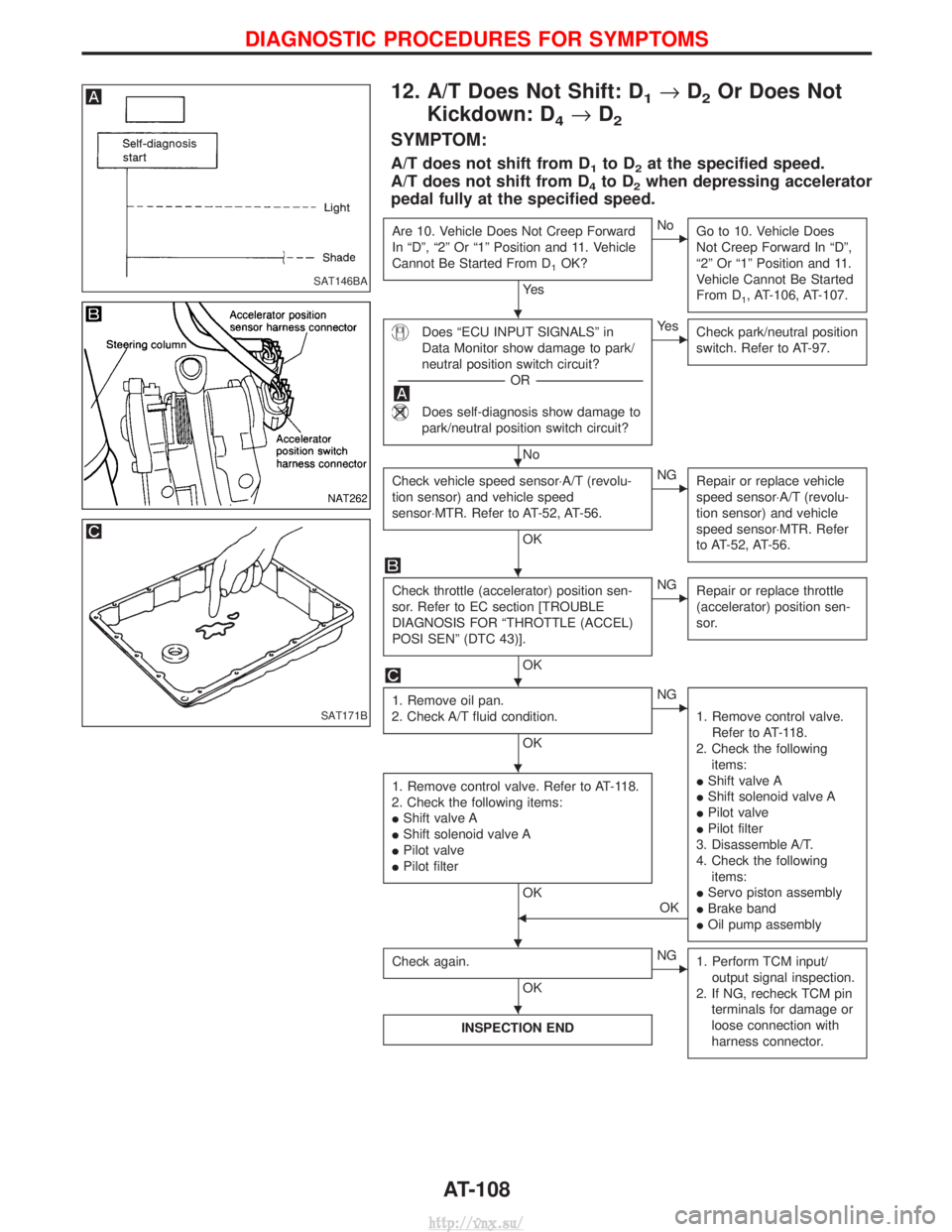
12. A/T Does Not Shift: D1®D2Or Does Not
Kickdown: D
4® D2
SYMPTOM:
A/T does not shift from D1to D2at the specified speed.
A/T does not shift from D
4to D2when depressing accelerator
pedal fully at the specified speed.
Are 10. Vehicle Does Not Creep Forward
In ªDº, ª2º Or ª1º Position and 11. Vehicle
Cannot Be Started From D
1OK?
Ye s
ENo Go to 10. Vehicle Does
Not Creep Forward In ªDº,
ª2º Or ª1º Position and 11.
Vehicle Cannot Be Started
From D
1, AT-106, AT-107.
Does ªECU INPUT SIGNALSº in
Data Monitor show damage to park/
neutral position switch circuit?
---------------------------------------------------------------------------------------------------------------------- -OR -----------------------------------------------------------------------------------------------------------------------
Does self-diagnosis show damage to
park/neutral position switch circuit?
No
EYe s
Check park/neutral position
switch. Refer to AT-97.
Check vehicle speed sensor×A/T (revolu-
tion sensor) and vehicle speed
sensor×MTR. Refer to AT-52, AT-56.
OK
ENGRepair or replace vehicle
speed sensor×A/T (revolu-
tion sensor) and vehicle
speed sensor×MTR. Refer
to AT-52, AT-56.
Check throttle (accelerator) position sen-
sor. Refer to EC section [TROUBLE
DIAGNOSIS FOR ªTHROTTLE (ACCEL)
POSI SENº (DTC 43)].
OK
ENGRepair or replace throttle
(accelerator) position sen-
sor.
1. Remove oil pan.
2. Check A/T fluid condition.
OK
ENG
1. Remove control valve.Refer to AT-118.
2. Check the following items:
I Shift valve A
I Shift solenoid valve A
I Pilot valve
I Pilot filter
3. Disassemble A/T.
4. Check the following items:
I Servo piston assembly
I Brake band
I Oil pump assembly
1. Remove control valve. Refer to AT-118.
2. Check the following items:
I Shift valve A
I Shift solenoid valve A
I Pilot valve
I Pilot filter
OK
FOK
Check again.
OK
ENG 1. Perform TCM input/
output signal inspection.
2. If NG, recheck TCM pin terminals for damage or
loose connection with
harness connector.
INSPECTION END
SAT146BA
NAT262
SAT171B
H
H
H
H
H
HH
H
DIAGNOSTIC PROCEDURES FOR SYMPTOMS
AT-108
http://vnx.su/
Page 922 of 1833
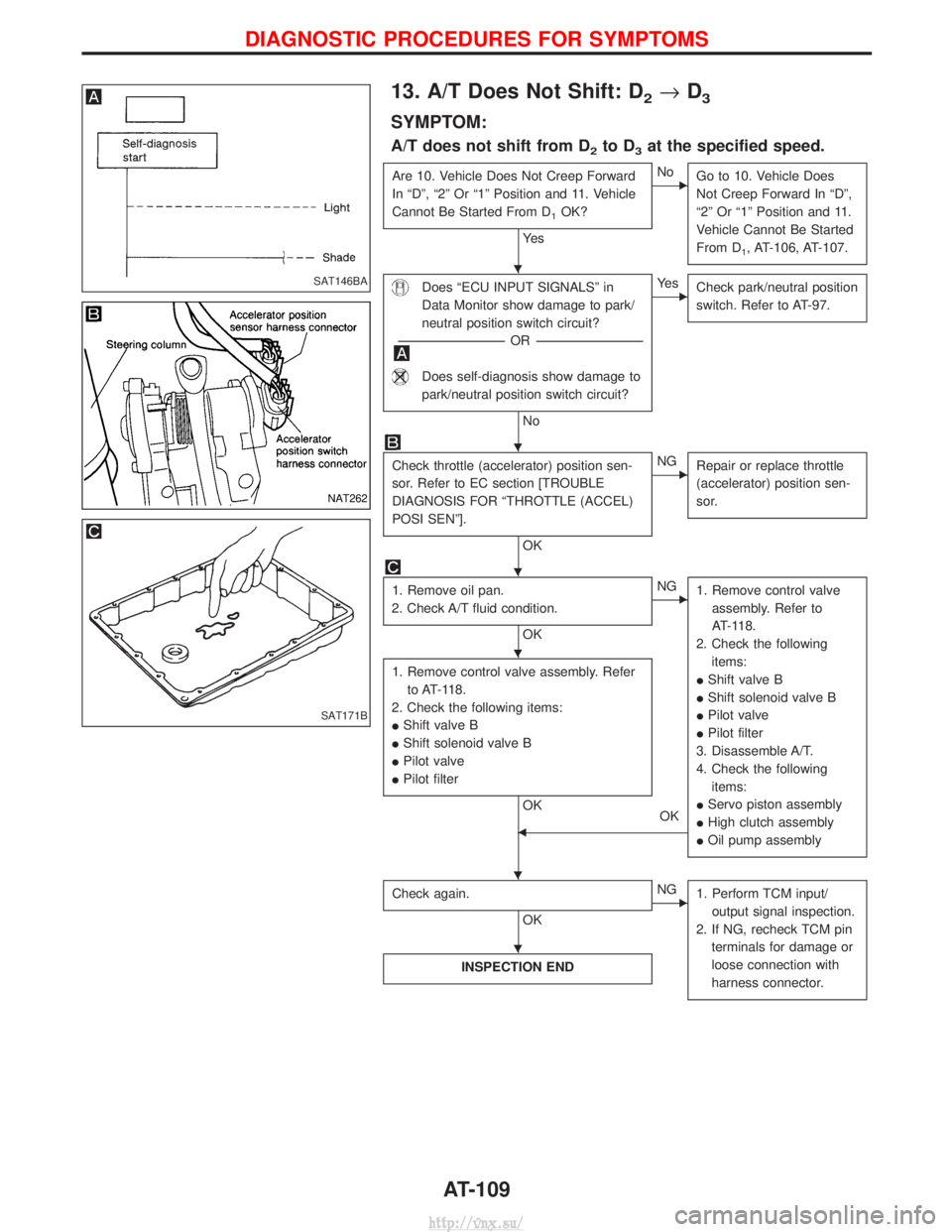
13. A/T Does Not Shift: D2®D3
SYMPTOM:
A/T does not shift from D2to D3at the specified speed.
Are 10. Vehicle Does Not Creep Forward
In ªDº, ª2º Or ª1º Position and 11. Vehicle
Cannot Be Started From D
1OK?
Ye s
ENo
Go to 10. Vehicle Does
Not Creep Forward In ªDº,
ª2º Or ª1º Position and 11.
Vehicle Cannot Be Started
From D
1, AT-106, AT-107.
Does ªECU INPUT SIGNALSº in
Data Monitor show damage to park/
neutral position switch circuit?
---------------------------------------------------------------------------------------------------------------------- -OR -----------------------------------------------------------------------------------------------------------------------
Does self-diagnosis show damage to
park/neutral position switch circuit?
No
EYe s
Check park/neutral position
switch. Refer to AT-97.
Check throttle (accelerator) position sen-
sor. Refer to EC section [TROUBLE
DIAGNOSIS FOR ªTHROTTLE (ACCEL)
POSI SENº].
OK
ENGRepair or replace throttle
(accelerator) position sen-
sor.
1. Remove oil pan.
2. Check A/T fluid condition.
OK
ENG 1. Remove control valve
assembly. Refer to
AT-118.
2. Check the following items:
I Shift valve B
I Shift solenoid valve B
I Pilot valve
I Pilot filter
3. Disassemble A/T.
4. Check the following items:
I Servo piston assembly
I High clutch assembly
I Oil pump assembly
1. Remove control valve assembly. Refer
to AT-118.
2. Check the following items:
I Shift valve B
I Shift solenoid valve B
I Pilot valve
I Pilot filter
OK
OK
F
Check again.
OK
ENG1. Perform TCM input/
output signal inspection.
2. If NG, recheck TCM pin terminals for damage or
loose connection with
harness connector.
INSPECTION END
SAT146BA
NAT262
SAT171B
H
H
H
H
HH
H
DIAGNOSTIC PROCEDURES FOR SYMPTOMS
AT-109
http://vnx.su/