Page 279 of 579
Terminal No.(wire color) ItemSignal
input/
output Condition
Reference value Example of symptom
(+) (þ) Ignition
switch Operation
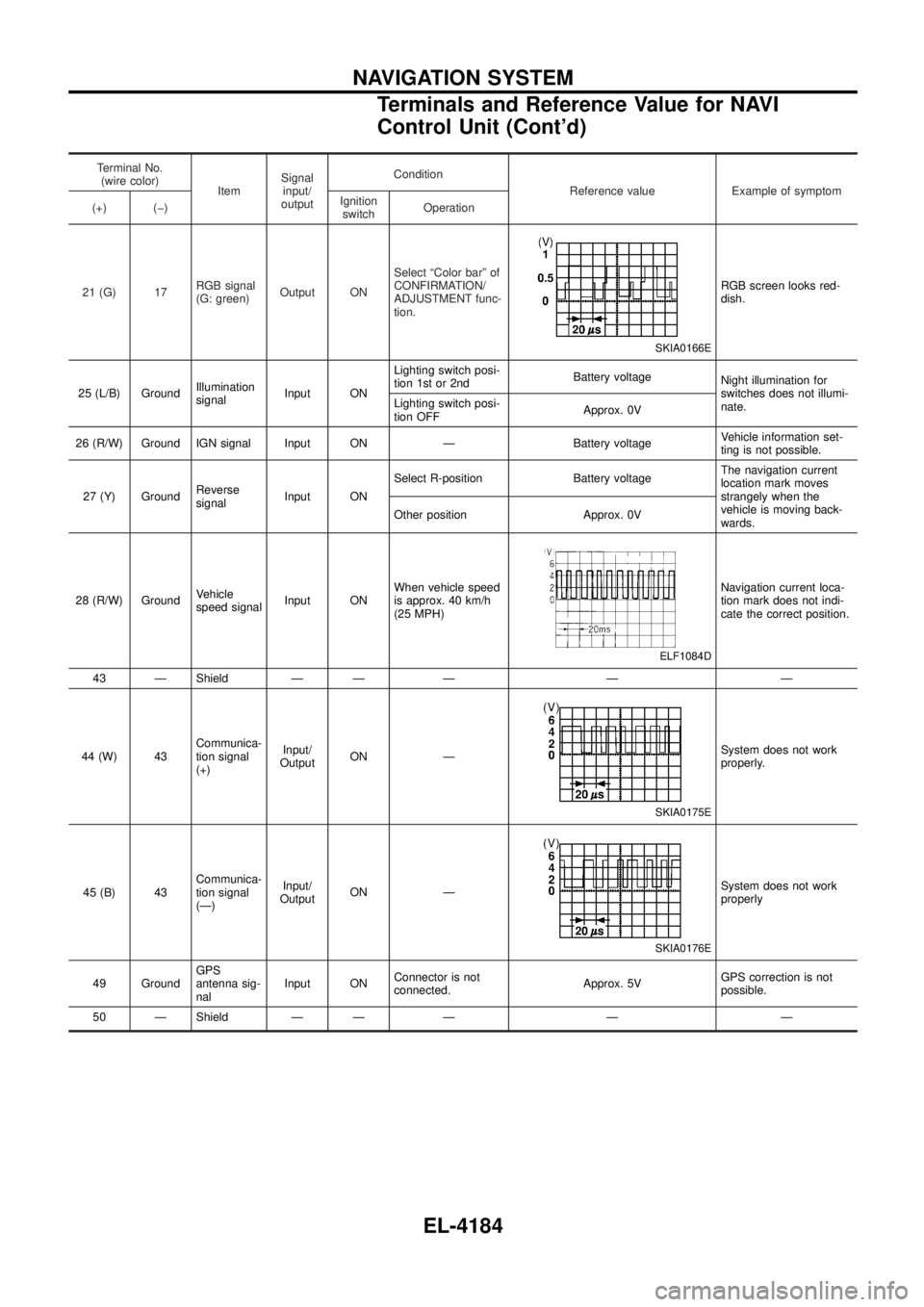
21 (G) 17 RGB signal
(G: green)Output ON Select ªColor barº of
CONFIRMATION/
ADJUSTMENT func-
tion.
SKIA0166E
RGB screen looks red-
dish.
25 (L/B) Ground Illumination
signalInput ON Lighting switch posi-
tion 1st or 2nd
Battery voltage
Night illumination for
switches does not illumi-
nate.
Lighting switch posi-
tion OFF Approx. 0V
26 (R/W) Ground IGN signal Input ON Ð Battery voltage Vehicle information set-
ting is not possible.
27 (Y) Ground Reverse
signalInput ON Select R-position Battery voltage
The navigation current
location mark moves
strangely when the
vehicle is moving back-
wards.
Other position Approx. 0V
28 (R/W) Ground Vehicle
speed signalInput ON When vehicle speed
is approx. 40 km/h
(25 MPH)
ELF1084D
Navigation current loca-
tion mark does not indi-
cate the correct position.
43 Ð Shield Ð Ð Ð Ð Ð
44 (W) 43 Communica-
tion signal
(+)Input/
Output ON Ð
SKIA0175E
System does not work
properly.
45 (B) 43 Communica-
tion signal
(Ð)Input/
Output ON Ð
SKIA0176E
System does not work
properly
49 Ground GPS
antenna sig-
nalInput ON
Connector is not
connected. Approx. 5VGPS correction is not
possible.
50 Ð Shield Ð Ð Ð Ð Ð
NAVIGATION SYSTEM
Terminals and Reference Value for NAVI
Control Unit (Cont'd)
EL-4184
Page 284 of 579
Self-Diagnosis Function
DESCRIPTION
+Diagnosis function consists of the self-diagnosis mode performed automatically and the CONFIRMATION/
ADJUSTMENT mode operated manually.
+ Self-diagnosis mode checks for connections between the units constituting this system, analyzes each
individual unit at the same time, and displays the results on the LCD screen.
+ CONFIRMATION/ADJUSTMENT mode is used to perform trouble diagnosis that require operation and
judgment by an operator (malfunction that cannot be automatically judged by the system), to check/change
the set value, and to display the History of Errors of the navigation system.
DIAGNOSIS ITEM
Mode Description
Self-diagnosis +
NAVI Control unit diagnosis (DVD-ROM drive will not be diagnosed when no
map DVD-ROM is in it.).
+ Performs diagnosis of each unit and connections between control unit and
GPS antenna, as well as between control unit and each unit.
Con®rmation/
Adjustment Display
Color tone and shading of the screen can be checked by the display of a color
bar and a gray scale.
Vehicle signals Analyzes the following vehicle signals: Vehicle speed signal, light signal, ignition
switch signal, and reverse signal.
Navigation Display Longi-
tude & Lati-
tude
Display the map. Use the joystick to adjust position. Longitude and latitude will be
displayed.
Speed Calibra-
tion Under ordinary conditions, the navigation system distance measuring function will
automatically compensate for minute decreases in wheel and tire diameter
caused by tire wear or low-pressure. Speed calibration immediately restores sys-
tem accuracy in cases such as when distance calibration is needed because of
the use of tire chains in inclement weather.
Angle Adjust-
ment Corrects difference between actual turning angle of a vehicle and turning angle of
the car mark on the display.
Initialize Loca-
tion This mode is for initializing the current location. Use when the vehicle is trans-
ported a long distance on a trailer, etc.
History of Errors Diagnosis results previously stored in the memory (before turning ignition switch
ON) are displayed in this mode. Time and location when/where the errors
occurred are also displayed.
Self-Diagnosis Mode
OPERATION PROCEDURE
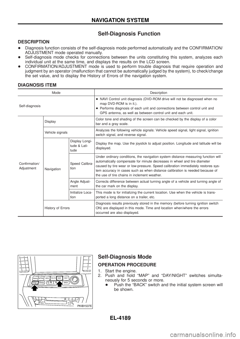
1. Start the engine.
2. Push and hold ªMAPº and ªDAY/NIGHTº switches simulta-
neously for 5 seconds or more.
+ Push the ªBACKº switch and the initial system screen will
be shown.
PKIB1537E
NAVIGATION SYSTEM
EL-4189
Page 289 of 579
Diagnosis item Display Condition Remarks
Vehicle speed ON Vehicle spee
d > 0 km/h (0 MPH)
Changes in indication may be delayed by
approx. 1.5 seconds. This is normal.
OFF Vehicle spee
d = 0 km/h (0 MPH)
Ð Ignition switch in ACC position
Light ON Lighting switch ON
Ð
OFF Lighting switch OFF
IGN ON Ignition switch ON
Ð
OFF Ignition switch ACC
Reverse ON Selector lever in R position
Changes in indication may be delayed by
approx. 1.5 seconds. This is normal.
OFF Selector lever in other than R position
Ð Ignition switch in ACC position
+ If vehicle speed is NG, refer to EL-4206.
+ If light is NG, refer to EL-4207.
+ If IGN is NG, refer to EL-4208.
+ If reverse is NG, refer to EL-4208.
NAVIGATION
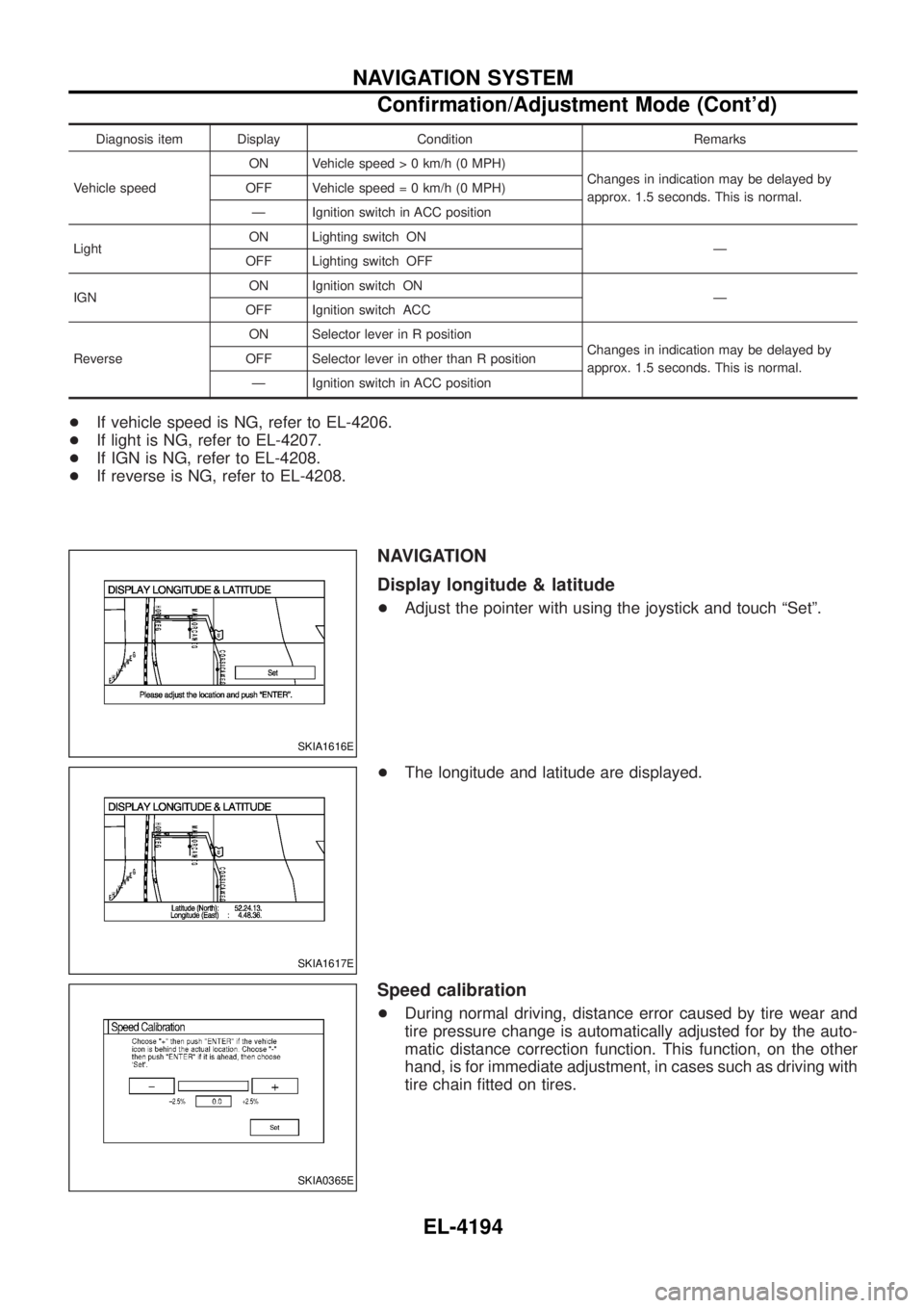
Display longitude & latitude
+Adjust the pointer with using the joystick and touch ªSetº.
+ The longitude and latitude are displayed.
Speed calibration
+During normal driving, distance error caused by tire wear and
tire pressure change is automatically adjusted for by the auto-
matic distance correction function. This function, on the other
hand, is for immediate adjustment, in cases such as driving with
tire chain ®tted on tires.
SKIA1616E
SKIA1617E
SKIA0365E
NAVIGATION SYSTEM
Con®rmation/Adjustment Mode (Cont'd)
EL-4194
Page 454 of 579
Installation
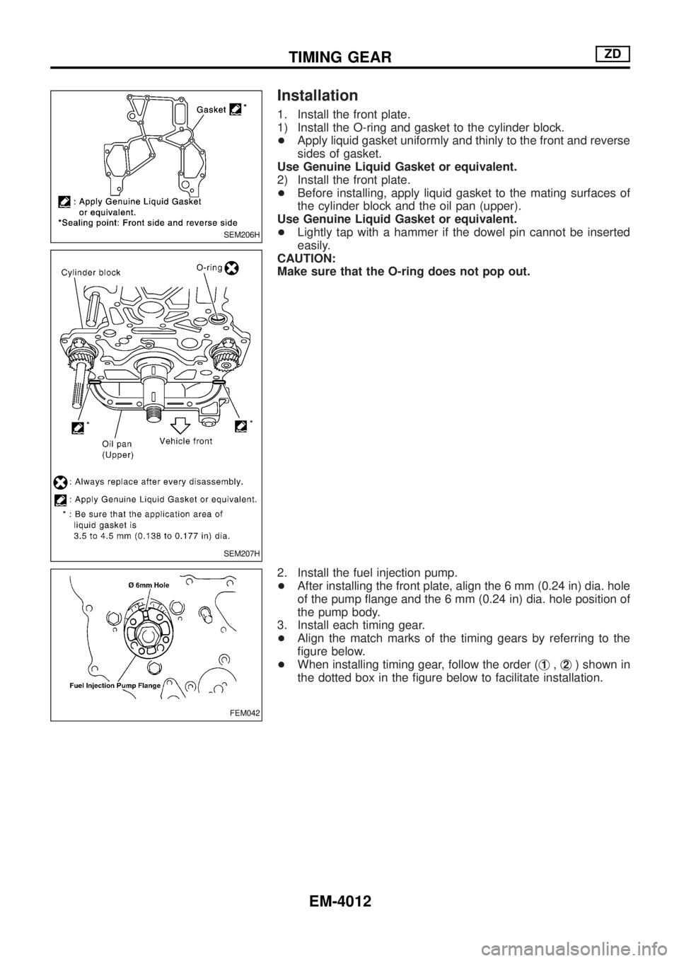
1. Install the front plate.
1) Install the O-ring and gasket to the cylinder block.
+Apply liquid gasket uniformly and thinly to the front and reverse
sides of gasket.
Use Genuine Liquid Gasket or equivalent.
2) Install the front plate.
+Before installing, apply liquid gasket to the mating surfaces of
the cylinder block and the oil pan (upper).
Use Genuine Liquid Gasket or equivalent.
+Lightly tap with a hammer if the dowel pin cannot be inserted
easily.
CAUTION:
Make sure that the O-ring does not pop out.
2. Install the fuel injection pump.
+After installing the front plate, align the 6 mm (0.24 in) dia. hole
of the pump ¯ange and the 6 mm (0.24 in) dia. hole position of
the pump body.
3. Install each timing gear.
+Align the match marks of the timing gears by referring to the
®gure below.
+When installing timing gear, follow the order (j
1,j2) shown in
the dotted box in the ®gure below to facilitate installation.
SEM206H
SEM207H
FEM042
TIMING GEARZD
EM-4012