2004 NISSAN PATROL fuel pressure
[x] Cancel search: fuel pressurePage 25 of 579

Body Rear End and Opener
+Bumper fascia is made of plastic. Do not use excessive force and be sure to keep oil away from it.
+Back door lock system adjustment: Adjust lock & striker so that they are in the center.
After adjustment, check back door lock operation.
+Back door hatch lock system adjustment: Adjust lock & striker so that they are in the center.
After adjustment, check back door hatch lock operation.
+Opener cable: Do not attempt to bend cable using excessive force.
+After installation, make sure that back door and fuel ®ller lid open smoothly.
WARNING:
+Be careful not to scratch back door stay and/or back door hatch stay when installing back door
and/or back door hatch. A scratched stay may cause gas leakage.
+The contents of the back door stay and back door hatch stay are under pressure. Do not take apart,
puncture, apply heat or allow ®re near them.
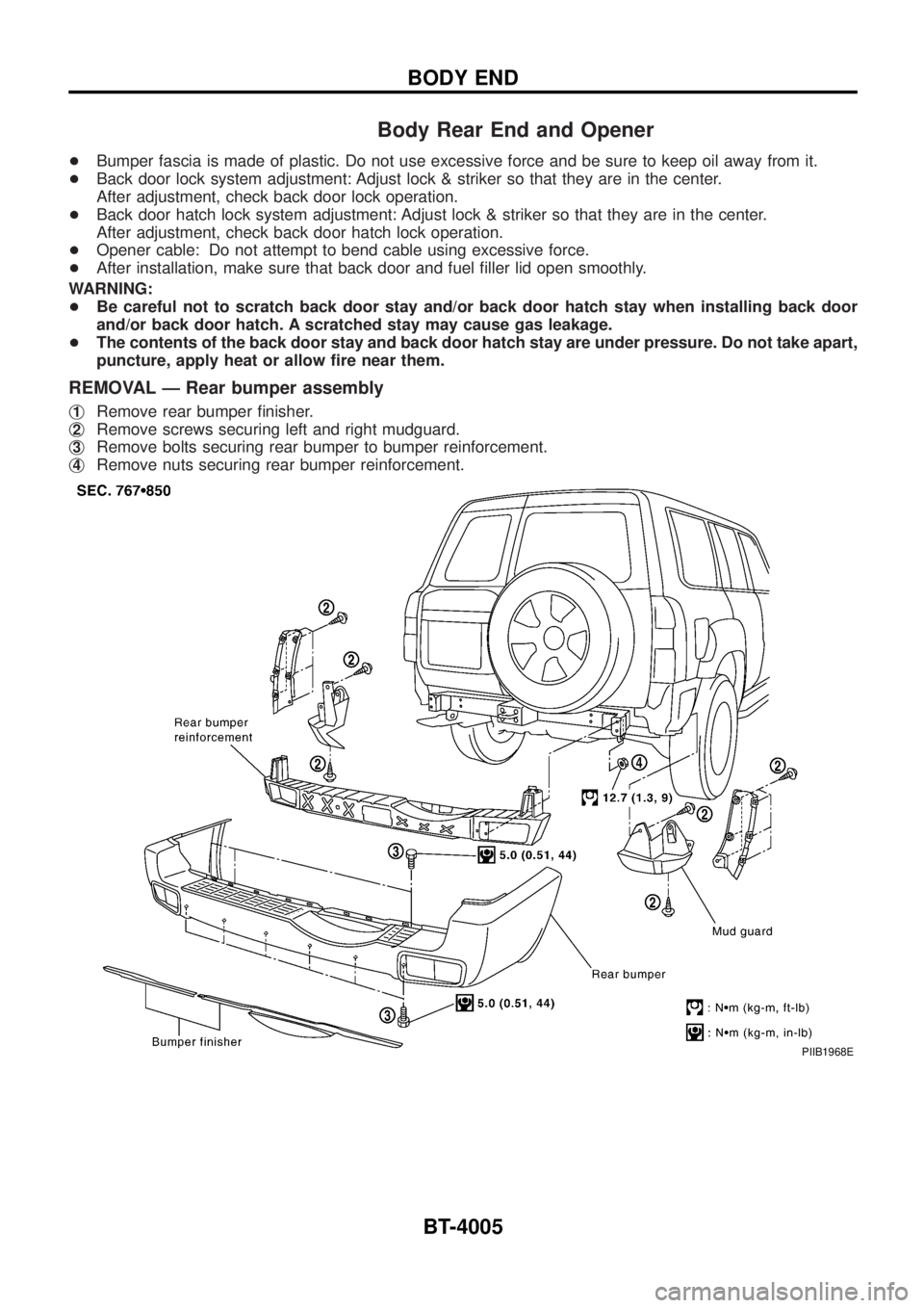
REMOVAL Ð Rear bumper assembly
j1Remove rear bumper ®nisher.
j
2Remove screws securing left and right mudguard.
j
3Remove bolts securing rear bumper to bumper reinforcement.
j
4Remove nuts securing rear bumper reinforcement.
PIIB1968E
BODY END
BT-4005
Page 79 of 579

TER-
MINAL
NO.WIRE
COLORITEM CONDITIONDATA (DC Voltage and Pulse
Signal)
38 B/Y Ignition switchIgnition switch ªOFFº
0V
Ignition switch ªONº
BATTERY VOLTAGE
(11 - 14V)
39
43B
BECM groundEngine is running.
Idle speedApproximately 0V
40 R/BElectronic control fuel
injection pumpEngine is running.
Warm-up condition
Idle speedApproximately 2.5V
42 L/G
Data link connectorEngine is running.
Idle speed (CONSULT-II is connected and
turned on)Approximately 0V
64 Y/GApproximately 0V
65 Y/RLess than 9V
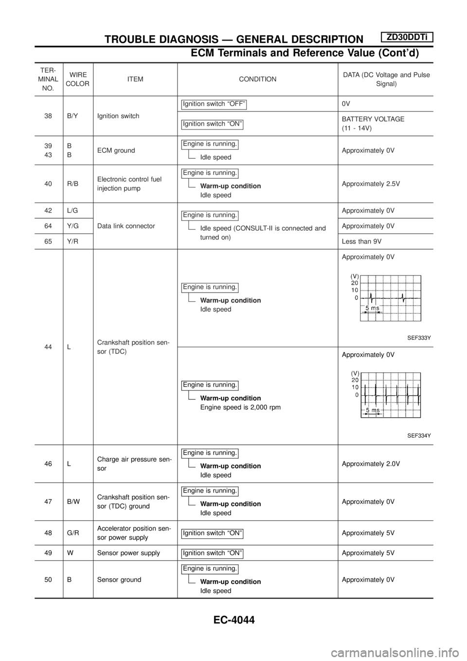
44 LCrankshaft position sen-
sor (TDC)Engine is running.
Warm-up condition
Idle speedApproximately 0V
SEF333Y
Engine is running.
Warm-up condition
Engine speed is 2,000 rpmApproximately 0V
SEF334Y
46 LCharge air pressure sen-
sorEngine is running.Warm-up condition
Idle speedApproximately 2.0V
47 B/WCrankshaft position sen-
sor (TDC) groundEngine is running.
Warm-up condition
Idle speedApproximately 0V
48 G/RAccelerator position sen-
sor power supplyIgnition switch ªONº
Approximately 5V
49 W Sensor power supply Ignition switch ªONº
Approximately 5V
50 B Sensor groundEngine is running.
Warm-up condition
Idle speedApproximately 0V
TROUBLE DIAGNOSIS Ð GENERAL DESCRIPTIONZD30DDTi
ECM Terminals and Reference Value (Cont'd)
EC-4044
Page 548 of 579

Illumination ..................................................EL-4079
Instrument panel .........................................BT-4006
Intake door motor .......................................HA-4037
Interior lamp ................................................EL-4088
K
Keyless entry system - See Multi-re-
mote control system ................................EL-4264
L
Length (Dimensions) ...................................GI-4008
License lamp ...............................................EL-4049
Line pressure test (A/T) ..............................AT-4014
LOAD - Wiring diagram .........EC-4008, 4016, 4025
Location of electrical units ..........................EL-4300
M
MAFS - Wiring diagram..............................EC-4049
Magnet clutch .............................................HA-4039
Maintenance...............................................MA-4003
Maintenance (engine) ................................MA-4003
Major overhaul (Transfer) .................TF-4002, 4003
Mass air ¯ow sensor (MAFS).....................EC-4047
Meter ...........................................................EL-4095
METER - Wiring diagram............................EL-4097
MIRROR - Wiring diagram..........................EL-4227
Mode door motor ........................................HA-4035
Model variation ............................................GI-4005
MULTI - Wiring diagram ...................EL-4264, 4266
Multi-remote control system........................EL-4264
N
NATS (Nissan anti-theft system) ......EL-4293, 4295
NATS - Wiring diagram ..........EL-4293, 4295, 4297
NAVI - Wiring diagram ................................EL-4175
Navigation System ......................................EL-4162
P
P/ANT - Wiring diagram..............................EL-4159
Parking lamp ...............................................EL-4049
POWER - Wiring diagram...........................EL-4006
Power door lock ..........................................EL-4244
Power supply routing ..................................EL-4005
Power window .............................................EL-4238
Pressure test (A/T) ......................................AT-4014Q
Quick-glow system .....................................EC-4031
R
Radio - See Audio.......................................EL-4136
R/COOL - Wiring diagram (front auto
A/C).........................................................HA-4055
R/COOL - Wiring diagram (front
manual A/C) ............................................HA-4057
Rear bumper ...............................................BT-4005
Rear seat ....................................................BT-4012
Rear seat belt .............................................RS-4013
Rear window defogger ................................EL-4126
REMOTE - Wiring diagram .........................EL-4155
R/FOG - Wiring diagram .............................EL-4064
R/HEAT - Wiring diagram ...........................HA-4003
Road wheel size ..........................................GI-4009
Room lamp - See Interior lamp ..................EL-4088
ROOM/L - Wiring diagram ..........................EL-4089
S
Seat belt, rear.............................................RS-4013
Seat, rear ....................................................BT-4012
Seat, second (2nd) .....................................BT-4012
Second (2nd) seat ......................................BT-4012
Shift schedule..............................................AT-4014
SMJ (super multiple junction) .......................Foldout
Speedometer...............................................EL-4095
SRS - Wiring diagram ................................RS-4003
STAB - Wiring diagram ..............................RA-4002
Stabilizer release device ............................RA-4002
Stabilizer release device - Wiring
diagram ...................................................RA-4002
Stall test (A/T) .............................................AT-4014
S/TANK - Wiring diagram ...........................FE-4004
Steering switch............................................EL-4036
Stop lamp ....................................................EL-4059
STOP/L - Wiring diagram............................EL-4059
Sub fuel tank control system ......................FE-4002
Super lock ...................................................EL-4290
Supplemental restraint system - Wiring
diagram ...................................................RS-4003
T
Tachometer .................................................EL-4095
Tail lamp ......................................................EL-4049
TAIL/L - Wiring diagram ..............................EL-4049
TCM circuit diagram ..........................AT-4002, 4011
Telephone....................................................EL-4161
THEFT - Wiring diagram ..................EL-4279, 4284
Theft warning system..................................EL-4278
ALPHABETICAL INDEX
IDX-4003