2004 NISSAN PATROL Condition
[x] Cancel search: ConditionPage 1 of 579
Edition: July 2004
Release: July 2004 (01)
Publication No.: SM4E00-1Y61E0E
Reference No.: 7711347233GENERAL INFORMATIONGI
MAINTENANCEMA
ENGINE MECHANICALEM
ENGINE LUBRICATION &
COOLING SYSTEMSLC
ENGINE CONTROL SYSTEMEC
ACCELERATOR CONTROL,
FUEL & EXHAUST SYSTEMFE
CLUTCHCL
MANUAL TRANSMISSIONMT
AUTOMATIC TRANSMISSIONAT
TRANSFERTF
PROPELLER SHAFT &
DIFFERENTIAL CARRIERPD
FRONT AXLE & FRONT SUSPENSIONFA
REAR AXLE & REAR SUSPENSIONRA
BRAKE SYSTEMBR
STEERING SYSTEMST
RESTRAINT SYSTEMRS
BODY & TRIMBT
HEATER & AIR CONDITIONERHA
ELECTRICAL SYSTEMEL
ALPHABETICAL INDEXIDX
PATROL
MODEL Y61 SERIES
NISSAN EUROPE S.A.S.
2004 NISSAN EUROPE S.A.S.
Produced in The Netherlands
Not to be reproduced in whole or in part
without the prior written permission of
Nissan Europe S.A.S., Paris, France.
QUICK REFERENCE INDEX
Page 17 of 579
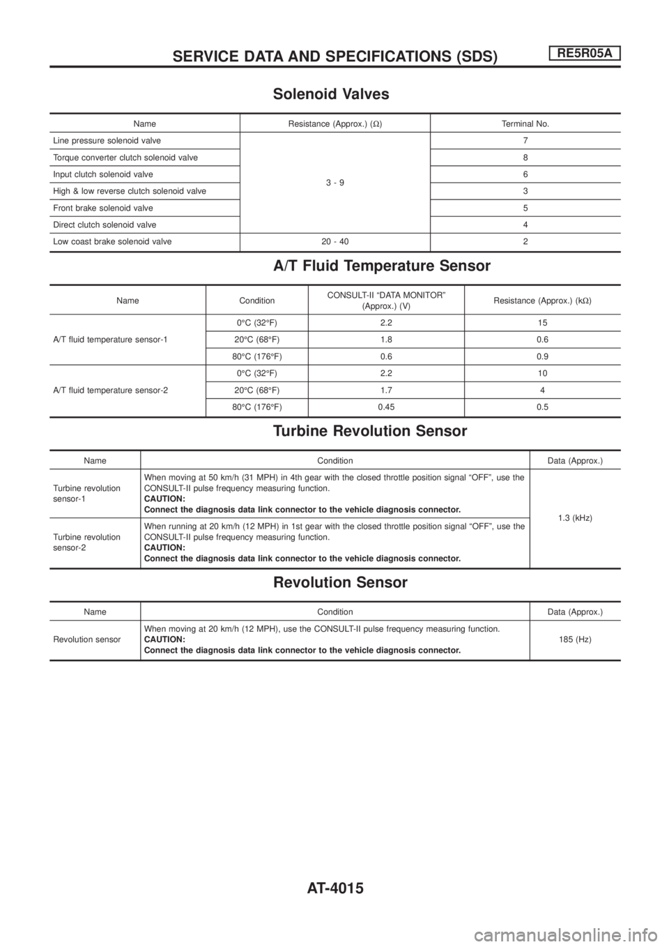
Solenoid Valves
Name Resistance (Approx.) (W) Terminal No.
Line pressure solenoid valve
3-97
Torque converter clutch solenoid valve8
Input clutch solenoid valve6
High & low reverse clutch solenoid valve3
Front brake solenoid valve5
Direct clutch solenoid valve4
Low coast brake solenoid valve 20 - 40 2
A/T Fluid Temperature Sensor
Name ConditionCONSULT-II ªDATA MONITORº
(Approx.) (V)Resistance (Approx.) (kW)
A/T ¯uid temperature sensor-10ÉC (32ÉF) 2.2 15
20ÉC (68ÉF) 1.8 0.6
80ÉC (176ÉF) 0.6 0.9
A/T ¯uid temperature sensor-20ÉC (32ÉF) 2.2 10
20ÉC (68ÉF) 1.7 4
80ÉC (176ÉF) 0.45 0.5
Turbine Revolution Sensor
Name Condition Data (Approx.)
Turbine revolution
sensor-1When moving at 50 km/h (31 MPH) in 4th gear with the closed throttle position signal ªOFFº, use the
CONSULT-II pulse frequency measuring function.
CAUTION:
Connect the diagnosis data link connector to the vehicle diagnosis connector.
1.3 (kHz)
Turbine revolution
sensor-2When running at 20 km/h (12 MPH) in 1st gear with the closed throttle position signal ªOFFº, use the
CONSULT-II pulse frequency measuring function.
CAUTION:
Connect the diagnosis data link connector to the vehicle diagnosis connector.
Revolution Sensor
Name Condition Data (Approx.)
Revolution sensorWhen moving at 20 km/h (12 MPH), use the CONSULT-II pulse frequency measuring function.
CAUTION:
Connect the diagnosis data link connector to the vehicle diagnosis connector.185 (Hz)
SERVICE DATA AND SPECIFICATIONS (SDS)RE5R05A
AT-4015
Page 36 of 579
SECTION
EC
MODIFICATION NOTICE:
+Wiring diagrams have been modi®ed.
+ MAF sensor has been changed for ZD30DDTi engine models.
CONTENTS
TB45E
ENGINE AND EMISSION CONTROL OVERALL
SYSTEM .....................................................................4003
Circuit Diagram ......................................................4003
TROUBLE DIAGNOSIS FOR NON-DETECTABLE
ITEMS ........................................................................\
.4004
Vehicle Speed Sensor (VSS) ................................4004
TB48DE M/T
ENGINE AND EMISSION CONTROL OVERALL
SYSTEM.....................................................................4005
Circuit Diagram ......................................................4005
VEHICLE SPEED SENSOR (VSS) ...........................4007
Wiring Diagram ......................................................4007
ELECTRICAL LOAD SIGNAL ...................................4008
Wiring Diagram ......................................................4008
Diagnostic Procedure ............................................4009
TB48DE A/T
ENGINE AND EMISSION CONTROL OVERALL
SYSTEM.....................................................................4013
Circuit Diagram ......................................................4013
SNOW MODE SWITCH .............................................4015
Wiring Diagram ......................................................4015
ELECTRICAL LOAD SIGNAL ...................................4016
Wiring Diagram ......................................................4016
Diagnostic Procedure ............................................4018
TB48DE A/T (WITH EURO-OBD)
TROUBLE DIAGNOSIS .............................................4022
Circuit Diagram ......................................................4022
SNOW MODE SWITCH .............................................4024
Wiring Diagram ......................................................4024
ELECTRICAL LOAD SIGNAL ...................................4025 Wiring Diagram ......................................................4025
Diagnostic Procedure ............................................4027
TD42
QUICK-GLOW SYSTEM ............................................4031
Circuit Diagram ......................................................4031
Wiring Diagram ......................................................4033
FAST IDLE CONTROL CIRCUIT ..............................4036
Wiring Diagram ......................................................4036
ZD30DDTi
ENGINE AND EMISSION CONTROL OVERALL
SYSTEM.....................................................................4037
Circuit Diagram ......................................................4037
TROUBLE DIAGNOSIS Ð GENERAL
DESCRIPTION ...........................................................4038
CONSULT-II Reference Value in Data Monitor
Mode ......................................................................4038
ECM Terminals and Reference Value ...................4040
DTC 0102 MASS AIR FLOW SEN ............................4047
Component Description .........................................4047
CONSULT-II Reference Value in Data Monitor
Mode ......................................................................4047
ECM Terminals and Reference Value ...................4047
On Board Diagnosis Logic.....................................4047
DTC Con®rmation Procedure ................................4048
Wiring Diagram ......................................................4049
Diagnostic Procedure ............................................4050
DTC 0104 VEHICLE SPEED SEN ............................4053
Wiring Diagram ......................................................4053
HEAT UP SWITCH ....................................................4054
Wiring Diagram ......................................................4054
Diagnostic Procedure ............................................4055
AIR CONDITIONER CONTROL ................................4058
Wiring Diagram ......................................................4058
EC-4001
Page 53 of 579
Diagnostic Procedure
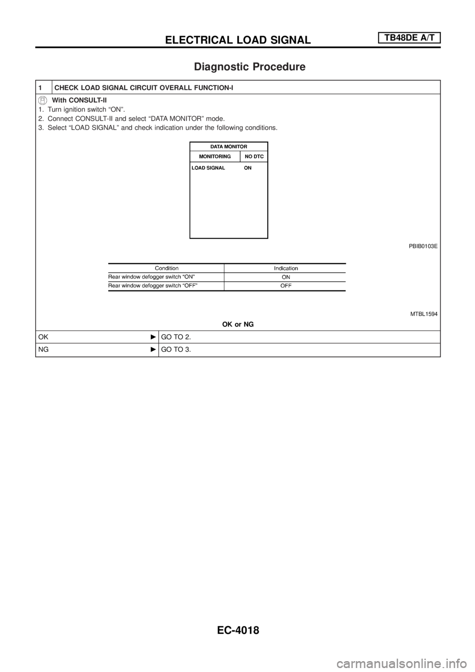
1 CHECK LOAD SIGNAL CIRCUIT OVERALL FUNCTION-I
With CONSULT-II
1. Turn ignition switch ªONº.
2. Connect CONSULT-II and select ªDATA MONITORº mode.
3. Select ªLOAD SIGNALº and check indication under the following conditions.
PBIB0103E
MTBL1594
OK or NG
OKcGO TO 2.
NGcGO TO 3.
ELECTRICAL LOAD SIGNALTB48DE A/T
EC-4018
Page 54 of 579
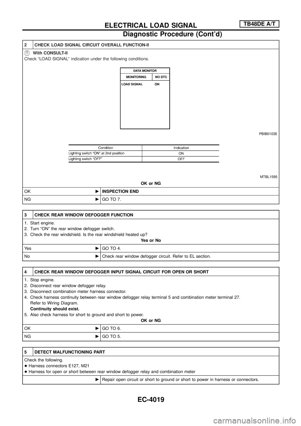
2 CHECK LOAD SIGNAL CIRCUIT OVERALL FUNCTION-II
With CONSULT-II
Check ªLOAD SIGNALº indication under the following conditions.
PBIB0103E
MTBL1595
OK or NG
OKcINSPECTION END
NGcGO TO 7.
3 CHECK REAR WINDOW DEFOGGER FUNCTION
1. Start engine.
2. Turn ªONº the rear window defogger switch.
3. Check the rear windshield. Is the rear windshield heated up?
YesorNo
Ye scGO TO 4.
NocCheck rear window defogger circuit. Refer to EL section.
4 CHECK REAR WINDOW DEFOGGER INPUT SIGNAL CIRCUIT FOR OPEN OR SHORT
1. Stop engine.
2. Disconnect rear window defogger relay.
3. Disconnect combination meter harness connector.
4. Check harness continuity between rear window defogger relay terminal 5 and combination meter terminal 27.
Refer to Wiring Diagram.
Continuity should exist.
5. Also check harness for short to ground and short to power.
OK or NG
OKcGO TO 6.
NGcGO TO 5.
5 DETECT MALFUNCTIONING PART
Check the following.
+Harness connectors E127, M21
+Harness for open or short between rear window defogger relay and combination meter
cRepair open circuit or short to ground or short to power in harness or connectors.
ELECTRICAL LOAD SIGNALTB48DE A/T
Diagnostic Procedure (Cont'd)
EC-4019
Page 62 of 579
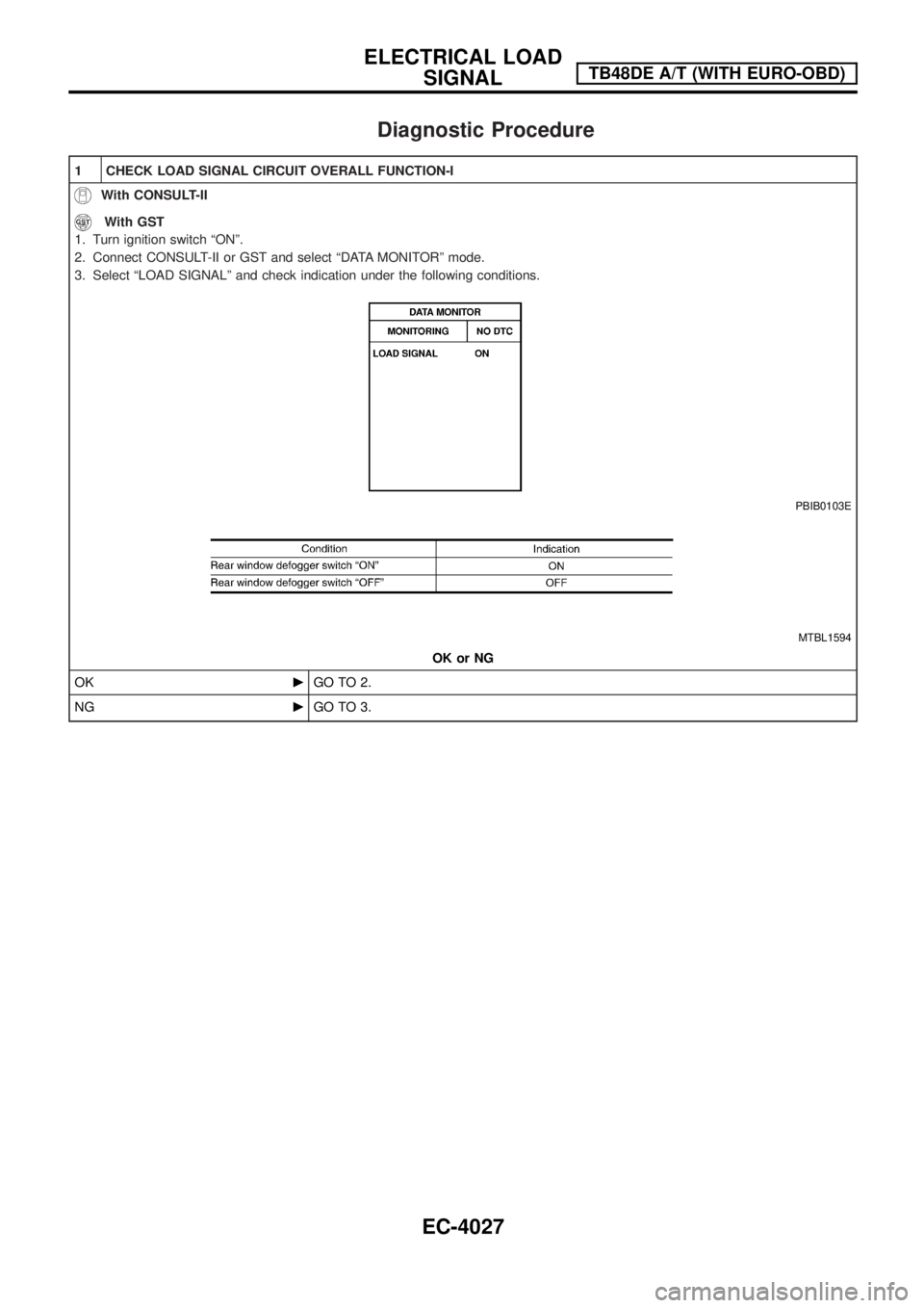
Diagnostic Procedure
1 CHECK LOAD SIGNAL CIRCUIT OVERALL FUNCTION-I
With CONSULT-II
With GST
1. Turn ignition switch ªONº.
2. Connect CONSULT-II or GST and select ªDATA MONITORº mode.
3. Select ªLOAD SIGNALº and check indication under the following conditions.
PBIB0103E
MTBL1594
OK or NG
OKcGO TO 2.
NGcGO TO 3.
ELECTRICAL LOAD
SIGNALTB48DE A/T (WITH EURO-OBD)
EC-4027
Page 63 of 579
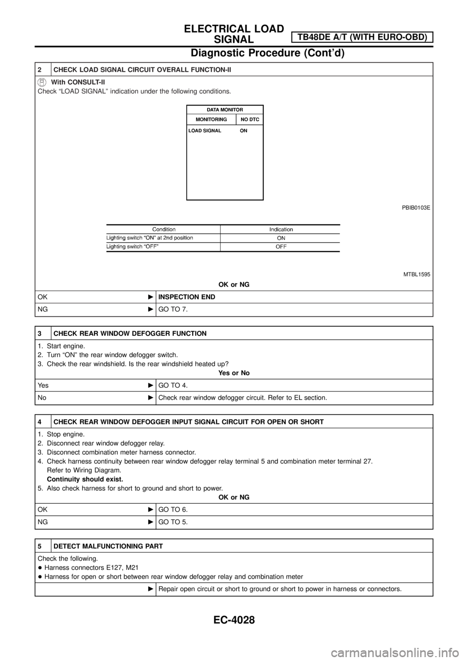
2 CHECK LOAD SIGNAL CIRCUIT OVERALL FUNCTION-II
With CONSULT-II
Check ªLOAD SIGNALº indication under the following conditions.
PBIB0103E
MTBL1595
OK or NG
OKcINSPECTION END
NGcGO TO 7.
3 CHECK REAR WINDOW DEFOGGER FUNCTION
1. Start engine.
2. Turn ªONº the rear window defogger switch.
3. Check the rear windshield. Is the rear windshield heated up?
YesorNo
Ye scGO TO 4.
NocCheck rear window defogger circuit. Refer to EL section.
4 CHECK REAR WINDOW DEFOGGER INPUT SIGNAL CIRCUIT FOR OPEN OR SHORT
1. Stop engine.
2. Disconnect rear window defogger relay.
3. Disconnect combination meter harness connector.
4. Check harness continuity between rear window defogger relay terminal 5 and combination meter terminal 27.
Refer to Wiring Diagram.
Continuity should exist.
5. Also check harness for short to ground and short to power.
OK or NG
OKcGO TO 6.
NGcGO TO 5.
5 DETECT MALFUNCTIONING PART
Check the following.
+Harness connectors E127, M21
+Harness for open or short between rear window defogger relay and combination meter
cRepair open circuit or short to ground or short to power in harness or connectors.
ELECTRICAL LOAD
SIGNALTB48DE A/T (WITH EURO-OBD)
Diagnostic Procedure (Cont'd)
EC-4028
Page 73 of 579
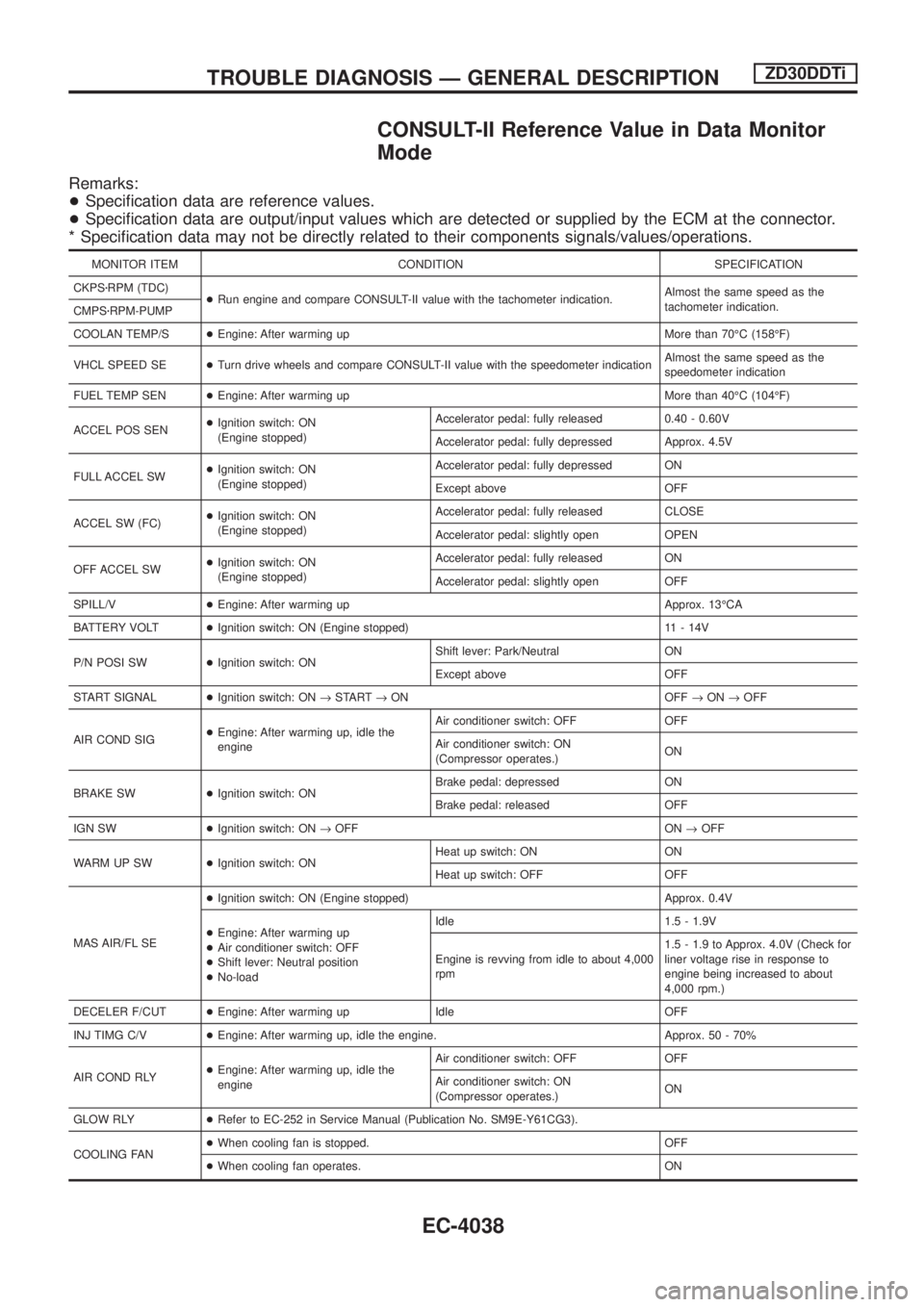
CONSULT-II Reference Value in Data Monitor
Mode
Remarks:
+Speci®cation data are reference values.
+Speci®cation data are output/input values which are detected or supplied by the ECM at the connector.
* Speci®cation data may not be directly related to their components signals/values/operations.
MONITOR ITEM CONDITION SPECIFICATION
CKPSzRPM (TDC)
+Run engine and compare CONSULT-II value with the tachometer indication.Almost the same speed as the
tachometer indication.
CMPSzRPM-PUMP
COOLAN TEMP/S+Engine: After warming up More than 70ÉC (158ÉF)
VHCL SPEED SE+Turn drive wheels and compare CONSULT-II value with the speedometer indicationAlmost the same speed as the
speedometer indication
FUEL TEMP SEN+Engine: After warming up More than 40ÉC (104ÉF)
ACCEL POS SEN+Ignition switch: ON
(Engine stopped)Accelerator pedal: fully released 0.40 - 0.60V
Accelerator pedal: fully depressed Approx. 4.5V
FULL ACCEL SW+Ignition switch: ON
(Engine stopped)Accelerator pedal: fully depressed ON
Except above OFF
ACCEL SW (FC)+Ignition switch: ON
(Engine stopped)Accelerator pedal: fully released CLOSE
Accelerator pedal: slightly open OPEN
OFF ACCEL SW+Ignition switch: ON
(Engine stopped)Accelerator pedal: fully released ON
Accelerator pedal: slightly open OFF
SPILL/V+Engine: After warming up Approx. 13ÉCA
BATTERY VOLT+Ignition switch: ON (Engine stopped) 11 - 14V
P/N POSI SW+Ignition switch: ONShift lever: Park/Neutral ON
Except above OFF
START SIGNAL+Ignition switch: ON®START®ON OFF®ON®OFF
AIR COND SIG+Engine: After warming up, idle the
engineAir conditioner switch: OFF OFF
Air conditioner switch: ON
(Compressor operates.)ON
BRAKE SW+Ignition switch: ONBrake pedal: depressed ON
Brake pedal: released OFF
IGN SW+Ignition switch: ON®OFF ON®OFF
WARM UP SW+Ignition switch: ONHeat up switch: ON ON
Heat up switch: OFF OFF
MAS AIR/FL SE+Ignition switch: ON (Engine stopped) Approx. 0.4V
+Engine: After warming up
+Air conditioner switch: OFF
+Shift lever: Neutral position
+No-loadIdle 1.5 - 1.9V
Engine is revving from idle to about 4,000
rpm1.5 - 1.9 to Approx. 4.0V (Check for
liner voltage rise in response to
engine being increased to about
4,000 rpm.)
DECELER F/CUT+Engine: After warming up Idle OFF
INJ TIMG C/V+Engine: After warming up, idle the engine. Approx. 50 - 70%
AIR COND RLY+Engine: After warming up, idle the
engineAir conditioner switch: OFF OFF
Air conditioner switch: ON
(Compressor operates.)ON
GLOW RLY+Refer to EC-252 in Service Manual (Publication No. SM9E-Y61CG3).
COOLING FAN+When cooling fan is stopped. OFF
+When cooling fan operates. ON
TROUBLE DIAGNOSIS Ð GENERAL DESCRIPTIONZD30DDTi
EC-4038