Page 63 of 579

2 CHECK LOAD SIGNAL CIRCUIT OVERALL FUNCTION-II
With CONSULT-II
Check ªLOAD SIGNALº indication under the following conditions.
PBIB0103E
MTBL1595
OK or NG
OKcINSPECTION END
NGcGO TO 7.
3 CHECK REAR WINDOW DEFOGGER FUNCTION
1. Start engine.
2. Turn ªONº the rear window defogger switch.
3. Check the rear windshield. Is the rear windshield heated up?
YesorNo
Ye scGO TO 4.
NocCheck rear window defogger circuit. Refer to EL section.
4 CHECK REAR WINDOW DEFOGGER INPUT SIGNAL CIRCUIT FOR OPEN OR SHORT
1. Stop engine.
2. Disconnect rear window defogger relay.
3. Disconnect combination meter harness connector.
4. Check harness continuity between rear window defogger relay terminal 5 and combination meter terminal 27.
Refer to Wiring Diagram.
Continuity should exist.
5. Also check harness for short to ground and short to power.
OK or NG
OKcGO TO 6.
NGcGO TO 5.
5 DETECT MALFUNCTIONING PART
Check the following.
+Harness connectors E127, M21
+Harness for open or short between rear window defogger relay and combination meter
cRepair open circuit or short to ground or short to power in harness or connectors.
ELECTRICAL LOAD
SIGNALTB48DE A/T (WITH EURO-OBD)
Diagnostic Procedure (Cont'd)
EC-4028
Page 68 of 579
Wiring Diagram
FOR COLD AREAS
TEC535M
QUICK-GLOW SYSTEMTD42
EC-4033
Page 69 of 579
TEC536M
QUICK-GLOW SYSTEMTD42
Wiring Diagram (Cont'd)
EC-4034
Page 70 of 579
TEC537M
QUICK-GLOW SYSTEMTD42
Wiring Diagram (Cont'd)
EC-4035
Page 71 of 579
Wiring Diagram
TEC526M
FAST IDLE CONTROL CIRCUITTD42
EC-4036
Page 84 of 579
Wiring Diagram
TEC528M
DTC 0102 MASS AIR FLOW SENZD30DDTi
EC-4049
Page 86 of 579

3 CHECK MAF SENSOR GROUND CIRCUIT FOR OPEN AND SHORT
1. Turn ignition switch ªOFFº.
2. Loosen and retighten engine ground screws.
SEF227Z
3. Disconnect ECM harness connector.
4. Disconnect TCM harness connector.
5. Check harness continuity between mass air ¯ow sensor terminal 3 and ECM terminal 50, TCM terminal 42. Refer to Wiring Dia-
gram.
Continuity should exist.
6. Also check harness for short to ground and short to power.
OK or NG
OKcGO TO 5.
NGcGO TO 4.
4 DETECT MALFUNCTIONING PART
Check the following.
+Harness connectors E230, F12
+Harness connectors M51, F6
+Harness connectors E106, M88
+Harness for open or short between mass air ¯ow sensor and ECM
+Harness for open or short between mass air ¯ow sensor and TCM (Transmission control module)
cRepair open circuit or short to ground or short to power in harness or connectors.
5 CHECK MAF SENSOR INPUT SIGNAL CIRCUIT FOR OPEN AND SHORT
1. Check harness continuity between mass air ¯ow sensor terminal 4 and ECM terminal 35. Refer to Wiring Diagram.
Continuity should exist.
2. Also check harness for short to ground and short to power.
OK or NG
OKcGO TO 7.
NGcGO TO 6.
6 DETECT MALFUNCTIONING PART
Check the following.
+Harness connectors E230, F12
+Harness for open or short between mass air ¯ow sensor and ECM
cRepair open circuit or short to ground or short to power in harness or connectors.
DTC 0102 MASS AIR FLOW SENZD30DDTi
Diagnostic Procedure (Cont'd)
EC-4051
Page 87 of 579

7 CHECK SHIELD CIRCUIT
1. Disconnect harness connectors E230, F12.
2. Check harness continuity between harness connector F12 terminal 5 and ground.
Refer to Wiring Diagram.
Continuity should exist.
3. Also check harness for short to power.
OK or NG
OKcGO TO 9.
NGcGO TO 8.
8 DETECT MALFUNCTIONING PART
Check the following.
+Joint connector-4
+Harness for open or short between harness connector F12 and ground
cRepair open circuit or short to power in harness or connectors.
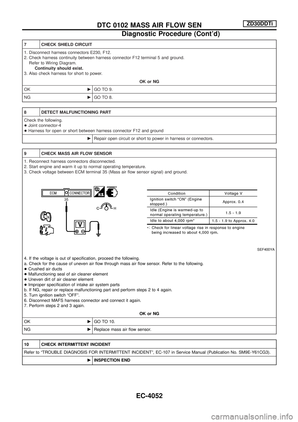
9 CHECK MASS AIR FLOW SENSOR
1. Reconnect harness connectors disconnected.
2. Start engine and warm it up to normal operating temperature.
3. Check voltage between ECM terminal 35 (Mass air ¯ow sensor signal) and ground.
SEF400YA
4. If the voltage is out of speci®cation, proceed the following.
a. Check for the cause of uneven air ¯ow through mass air ¯ow sensor. Refer to the following.
+Crushed air ducts
+Malfunctioning seal of air cleaner element
+Uneven dirt of air cleaner element
+Improper speci®cation of intake air system parts
b. If NG, repair or replace malfunctioning part and perform steps 2 to 4 again.
5. Turn ignition switch ªOFFº.
6. Disconnect MAFS harness connector and connect it again.
7. Perform steps 2 and 3 again.
OK or NG
OKcGO TO 10.
NGcReplace mass air ¯ow sensor.
10 CHECK INTERMITTENT INCIDENT
Refer to ªTROUBLE DIAGNOSIS FOR INTERMITTENT INCIDENTº, EC-107 in Service Manual (Publication No. SM9E-Y61CG3).
cINSPECTION END
DTC 0102 MASS AIR FLOW SENZD30DDTi
Diagnostic Procedure (Cont'd)
EC-4052