Page 3269 of 3870
Q: Is TCL/ASC-ECU connector A-32 damaged?
YES: Repair or replace the damaged component(s). Then go to Step 8.
NO: An open or short circuit may be present in the solenoid valve power
supply circuit. Repair the wiring harness between TCL/ASC-ECU
connector A-32 terminal 33 and fusible link No. 3. Then go to Step 8.
STEP 5. Measure the resistance at TCL/ASC-ECU connector A-32.
1. Disconnect the connector A-32, and connect special tool ABS Check
Harness (MB991952) to the wiring harness-side connector.
2. Measure the resistance between terminal 34 and ground. It should be 2
ohms or less. NOTE: Do not connect special tool ABS Check Harness
(MB991952) to the TCL/ASC-ECU.
2004 Mitsubishi Endeavor LS
2004 BRAKES Traction Control, Active Skid Control System - Endeavor
Page 3277 of 3870
6. Turn the ignition switch to the "LOCK" (OFF) position.
Q: Is DTC C1266, C1273 or C1274 set?
YES: Go to Step 1.
NO: The procedure is complete.
DTC C1278: VALVE POWER CIRCUIT STUCK OFF, DTC C1279: VALVE POWER CIRCUIT STUCK ON Fig. 114: Solenoid Valve And Motor Power Supply Circuit Diagram & Connector Identification
2004 Mitsubishi Endeavor LS
2004 BRAKES Traction Control, Active Skid Control System - Endeavor
Page 3278 of 3870

Courtesy of MITSUBISHI MOTOR SALES OF AMERICA
.
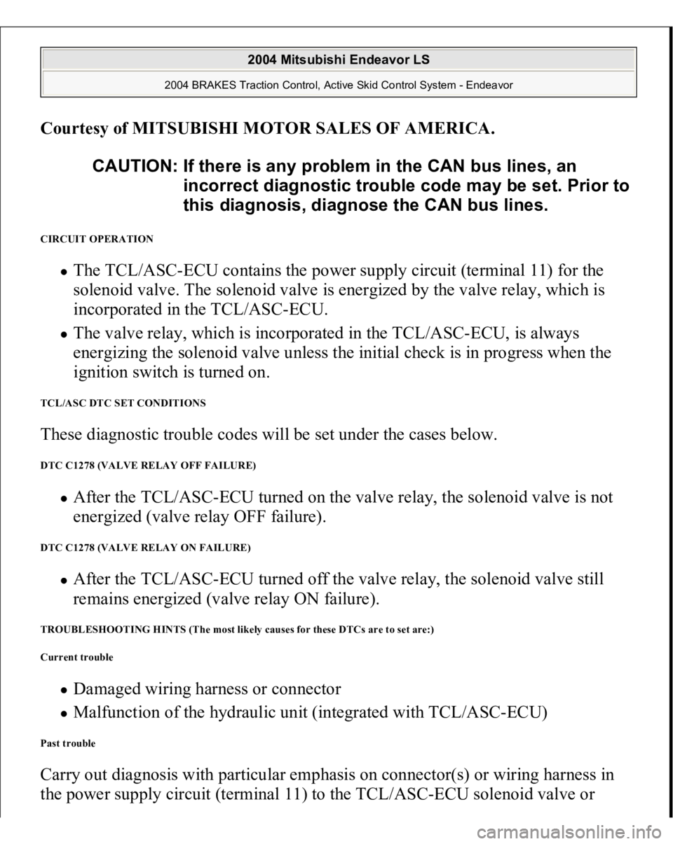
CIRCUIT OPERATION
The TCL/ASC-ECU contains the power supply circuit (terminal 11) for the
solenoid valve. The solenoid valve is energized by the valve relay, which is
incorporated in the TCL/ASC-ECU. The valve relay, which is incorporated in the TCL/ASC-ECU, is always
energizing the solenoid valve unless the initial check is in progress when the
ignition switch is turned on.
TCL/ASC DTC SET CONDITIONS These diagnostic trouble codes will be set under the cases below. DTC C1278 (VALVE RELAY OFF FAILURE)
After the TCL/ASC-ECU turned on the valve relay, the solenoid valve is not
energized (valve relay OFF failure).
DTC C1278 (VALVE RELAY ON FAILURE)
After the TCL/ASC-ECU turned off the valve relay, the solenoid valve still
remains energized (valve relay ON failure).
TROUBLESHOOTING HINTS (The most likely causes for these DTCs are to set are:)
Current trouble
Damaged wiring harness or connector Malfunction of the hydraulic unit (integrated with TCL/ASC-ECU)
Past trouble Carry out diagnosis with particular emphasis on connector(s) or wiring harness in
the power supply circuit (terminal 11) to the TCL/AS
C-ECU solenoid valve or CAUTION: If there is any problem in the CAN bus lines, an
incorrect diagnostic trouble code may be set. Prior to
this diagnosis, diagnose the CAN bus lines.
2004 Mitsubishi Endeavor LS
2004 BRAKES Traction Control, Active Skid Control System - Endeavor
Page 3287 of 3870
Q: Is TCL/ASC-ECU connector A-32 damaged?
YES: Repair or replace the damaged component(s). Then go to Step 8.
NO: An open or short circuit may be present in the solenoid valve power
supply circuit. Repair the wiring harness between TCL/ASC-ECU
connector A-32 terminal 11 and fusible link No. 3. Then go to Step 8.
STEP 5. Measure the resistance at TCL/ASC-ECU connector A-32.
1. Disconnect the connector A-32, and connect special tool ABS Check
Harness (MB991952) to the wiring harness-side connector.
2. Measure the resistance between terminal 12 and ground. It should be 2
ohms or less. NOTE: Do not connect special tool ABS Check Harness
(MB991952) to the TCL/ASC-ECU.
2004 Mitsubishi Endeavor LS
2004 BRAKES Traction Control, Active Skid Control System - Endeavor
Page 3537 of 3870

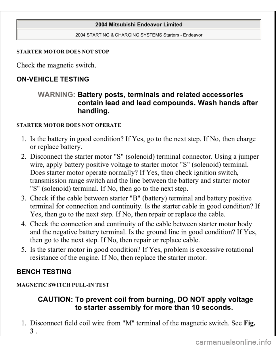
STARTER MOTOR DOES NOT STOPCheck the magnetic switch. ON-VEHICLE TESTING STARTER MOTOR DOES NOT OPERATE 1. Is the battery in good condition? If Yes, go to the next step. If No, then charge
or replace battery.
2. Disconnect the starter motor "S" (solenoid) terminal connector. Using a jumper
wire, apply battery positive voltage to starter motor "S" (solenoid) terminal.
Does starter motor operate normally? If Yes, then check ignition switch,
transmission range switch and the line between the battery and starter motor
"S" (solenoid) terminal. If No, then go to the next step.
3. Check if the cable between starter "B" (battery) terminal and battery positive
terminal for connection and continuity. Is the starter cable in good condition? I
f
Yes, then go to the next step. If No, then repair or replace the cable.
4. Check the connection and continuity of the cable between starter motor body
and the negative battery terminal. Is the ground line in good condition? If Yes,
then go to the next step. If No, then repair or replace cable.
5. Is the starter motor in good condition? If Yes, problem is excessive rotational
resistance of the engine. If No, then replace the starter motor.
BENCH TESTING MAGNETIC SWITCH PULL-IN TEST 1. Disconnect field coil wire from "M" terminal of the magnetic switch. See Fig.
3 . WARNING:Battery posts, terminals and related accessories
contain lead and lead compounds. Wash hands after
handling.
CAUTION: To prevent coil from burning, DO NOT apply voltage
to starter assembly for more than 10 seconds.
2004 Mitsubishi Endeavor Limited
2004 STARTING & CHARGING SYSTEMS Starters - Endeavor