Page 215 of 3870
Courtesy of MITSUBISHI MOTOR SALES OF AMERICA
.
2. Turn the ignition switch to the "ON" position.
3. Diagnose the CAN bus line.
Q: Is the check result satisfactory?
YES: Check and repair the power supply circuit system (Refer to
INSPECTION PROCEDURE 2: POWER SUPPLY CIRCUIT
SYSTEM
).
NO: Repair the CAN bus lines (Refer to DIAGNOSTIC TROUBLE
CODE DIAGNOSIS
or DIAGNOSIS < VEHICLES WITHOUT
ADVANCED AIR BAG
).
INSPECTION PROCEDURE 2: POWER SUPPLY CIRCUIT SYSTEM
2004 Mitsubishi Endeavor LS
2004 BRAKES Anti-Lock Braking System (ABS) - Endeavor
Page 232 of 3870
Fig. 134: EBO And ABS Warning Light Circuit Diagram
Courtesy of MITSUBISHI MOTOR SALES OF AMERICA.
Fig. 135: Identifying Connectors: A
-02, C
-04, C
-31, C
-101, C
-102, C
-103, C
-
211, C
-215
Courtesy of MITSUBISHI MOTOR SALES OF AMERICA.
TECHNICAL DESCRIPTION (COMMENT)
The ABS-ECU sends the ABS warning light and the brake warning light
signals to the combination meter via the CAN communication. This may be caused by faults in the CAN bus line, the combination meter or
the ABS-ECU.
TROUBLESHOOTING HINTS (THE MOST LIKELY CAUSES FOR THIS CASE:)
Damaged wiring harness or connector Combination meter defect Malfunction of the hydraulic unit (integrated with ABS-ECU)
DIAGNOSIS
2004 Mitsubishi Endeavor LS
2004 BRAKES Anti-Lock Braking System (ABS) - Endeavor
Page 233 of 3870
Required Special Tools:
MB991958: Scan Tool (MUT-III Sub Assembly)
MB991824: Vehicle Communication Interface (V. C. I.) MB991827: MUT-III USB Cable MB991910: MUT-III Main Harness A
STEP 1. Using scan tool MB991958, diagnose the CAN bus line.
Use scan tool MB991958 to the diagnose the CAN bus lines.
1. Connect scan tool MB991958 to the data link connec
tor. CAUTION: To prevent damage to scan tool MB991958,
always turn the ignition switch to the
"LOCK" (OFF) position before connecting or
disconnecting scan tool MB991958.
2004 Mitsubishi Endeavor LS
2004 BRAKES Anti-Lock Braking System (ABS) - Endeavor
Page 235 of 3870
2. Turn the ignition switch to the "ON" position.
3. Diagnose the CAN bus line.
Q: Is the check result satisfactory?
YES: Go to Step 2.
NO: Repair the CAN bus lines (Refer to DIAGNOSTIC TROUBLE
CODE DIAGNOSIS
or DIAGNOSIS < VEHICLES WITHOUT
ADVANCED AIR BAG
). Repair the CAN bus lines, and then go to Step
2.
STEP 2. Using scan tool MB991958, read the combination meter
diagnostic trouble code.
Use scan tool MB991958 to check whether combination meter DTC U1102 has
been set.
1. Connect scan tool MB991958 to the data link connec
tor. CAUTION: To prevent damage to scan tool MB991958,
always turn the ignition switch to the
"LOCK" (OFF) position before connecting or
disconnecting scan tool MB991958.
2004 Mitsubishi Endeavor LS
2004 BRAKES Anti-Lock Braking System (ABS) - Endeavor
Page 309 of 3870

DIAGNOSTIC TESTS INSPECTION PROCEDURE 1 No communication between scan tool and all systems is most likely in power
supply or ground circuits to Data Link Connector (DLC). Check wire harness and
connectors for damage and loose connections. See WIRING DIAGRAMS
.
INSPECTION PROCEDURE 2 1. Before proceeding, see AIR BAG SAFETY PRECAUTIONS
. Disconnect
SRS ECU connector C-26. See SRS ELECTRONIC CONTROL UNIT
(SRS ECU)
under REMOVAL & INSTALLATION. See Fig. 19
. Measure
resistance between SRS ECU connector C-26, terminal No. 20 (Orange/Blue
wire) and Data Link Connector (DLC), terminal No. 7 (Orange/Blue wire). See
Fig. 20
& Fig. 21
. If resistance is more than 2 ohms, go to next step. If
resistance is 2 ohms or less, go to step 4 .
2. Measure resistance between SRS ECU connector C-26, terminal No. 15 (Black
wire) and ground. If resistance is less than 2 ohms, go to next step. If resistance
is 2 ohms or more, go to step 5 .
3. Connect negative battery cable. Turn ignition on. Measure voltage between
ground and SRS ECU connector C-26, terminals No. 13 (Black/White wire)
and No. 16 (Black/Yellow wire). If voltage is less than 9 volts at either
terminal, go to step 6 . If voltage at both terminals is 9 volts or more, recheck
trouble s
ymptom. If s
ymptom still exists, re
place SRS ECU. Go to ste
p 7 .
B1547
Cut off for passenger-side air bag module
B1552
Changing circuit short
B1553
Changing circuit open
B1554
SG by-pass circuit malfunction
B1555
SG by-pass circuit (FET) open
B1556
Seat slide sensor malfunction
B1557
SRS ECU ASIC
B1558
Occupant classification ECU ID cord malfunction
U1073
BUS of
f
2004 Mitsubishi Endeavor Limited
2004 ACCESSORIES/SAFETY EQUIPMENT Mitsubishi - Air Bag Restraint Systems
Page 346 of 3870

then retrieve DTCs. If DTC 94 is retrieved, go to step 1 . If DTC 94 is not
retrieved, system is normal at this time. Intermittent condition may exist.
DIAGNOSTIC TESTS (DUAL-STAGE AIR BAG SYSTEM) INSPECTION PROCEDURE 1 Connect scan tool to Data Link Connector (DLC). See INITIAL SRS DIAGNOSTIC PROCEDURE
under DIAGNOSTICS. Turn ignition on. If scan
tool is able to diagnose CAN bus lines and CAN bus lines are satisfactory, inspect
and repair power circuits. Go to INSPECTION PROCEDURE 2
. If scan tool
cannot diagnose CAN bus lines, inspect and repair CAN bus lines.
INSPECTION PROCEDURE 2 1. Connect scan tool to Data Link Connector (DLC). See INITIAL SRS
DIAGNOSTIC PROCEDURE
under DIAGNOSTICS. Disconnect SRS ECU
connector C-26. See SRS ELECTRONIC CONTROL UNIT (SRS ECU)
under REMOVAL & INSTALLATION. See Fig. 30
. Measure resistance
between ground and connector C-26, terminal No. 40 (Black wire). If
resistance is 2 ohms or less, go to next step. If resistance is more than 2 ohms,
repair wiring harness between SRS ECU and ground. See WIRE REPAIR
.
2. Inspect Black/White wire and Black/Yellow wire between connector C-26 and
ignition switch connector C-308, including junction block connectors C-211
and C-215. See Fig. 22
. If wires are okay, go to next step. If wires are not
okay, replace wire harness.
3. Inspect battery. If battery is in good condition, go to next step. If battery is not
in good condition, charge or replace battery as appropriate. Go to step 5 .
4. Inspect charging system. If charging system is okay, go to next step. If
charging system is not okay, repair charging system as appropriate. Go to next
step.
5. Retest SRS system. If scan tool can communicate with SRS ECU, an
intermittent condition may have existed. If scan tool cannot communicate with
NOTE: If scan tool cannot communicate with SRS ECU, CAN bus
line may be defective.
2004 Mitsubishi Endeavor Limited
2004 ACCESSORIES/SAFETY EQUIPMENT Mitsubishi - Air Bag Restraint Systems
Page 348 of 3870

1. Connect scan tool to Data Link Connector (DLC). See INITIAL SRS
DIAGNOSTIC PROCEDURE
under DIAGNOSTICS. If scan tool is able to
diagnose CAN bus lines and CAN bus lines are satisfactory, go to next step. If
scan tool cannot diagnose CAN bus lines, repair CAN bus lines. Go to next
step.
2. Using scan tool, retrieve combination meter Diagnostic Trouble Codes (DTCs).
If DTC U1112 is retrieved, replace SRS ECU. If DTC U1112 is not retrieved,
replace combination meter.
INSPECTION PROCEDURE 4 1. Connect scan tool to Data Link Connector (DLC). See INITIAL SRS
DIAGNOSTIC PROCEDURE
under DIAGNOSTICS. If scan tool is able to
diagnose CAN bus lines and CAN bus lines are satisfactory, go to next step. If
scan tool cannot diagnose CAN bus lines, repair CAN bus lines. Go to next
step.
2. Using scan tool, retrieve combination meter Diagnostic Trouble Codes (DTCs).
If DTC U1112 is retrieved, replace SRS ECU. If DTC U1112 is not retrieved,
replace combination meter.
DTC B1400: DRIVER-SIDE AIR BAG MODULE FIRST-STAGE SHORT CIRCUIT 1. Connect scan tool to Data Link Connector (DLC). See INITIAL SRS
DIAGNOSTIC PROCEDURE
under DIAGNOSTICS. If scan tool is able to
diagnose CAN bus lines and CAN bus lines are satisfactory, go to next step. If
scan tool cannot diagnose CAN bus lines, repair CAN bus lines. Go to next
step.
2. Erase, then retrieve DTCs. Turn ignition off. If DTC B1400 is retrieved, go to
next step. If DTC B1400 is not retrieved, an intermittent condition may exist.
3. Turn ignition on. If DTC B1519 is retrieved by scan tool, go to next step. If
DTC B1519 is not retrieved by scan tool, go to step 5 .
4. Inspect SRS ECU connector C-26. See SRS ELECTRONIC CONTROL
UNIT (SRS ECU)
under REMOVAL & INSTALLATION. See Fig. 30
. If
connector is connected correctly, go to next step. If connector is not connected
correctly, reconnect correctly. Go to step 1
0.
2004 Mitsubishi Endeavor Limited
2004 ACCESSORIES/SAFETY EQUIPMENT Mitsubishi - Air Bag Restraint Systems
Page 351 of 3870

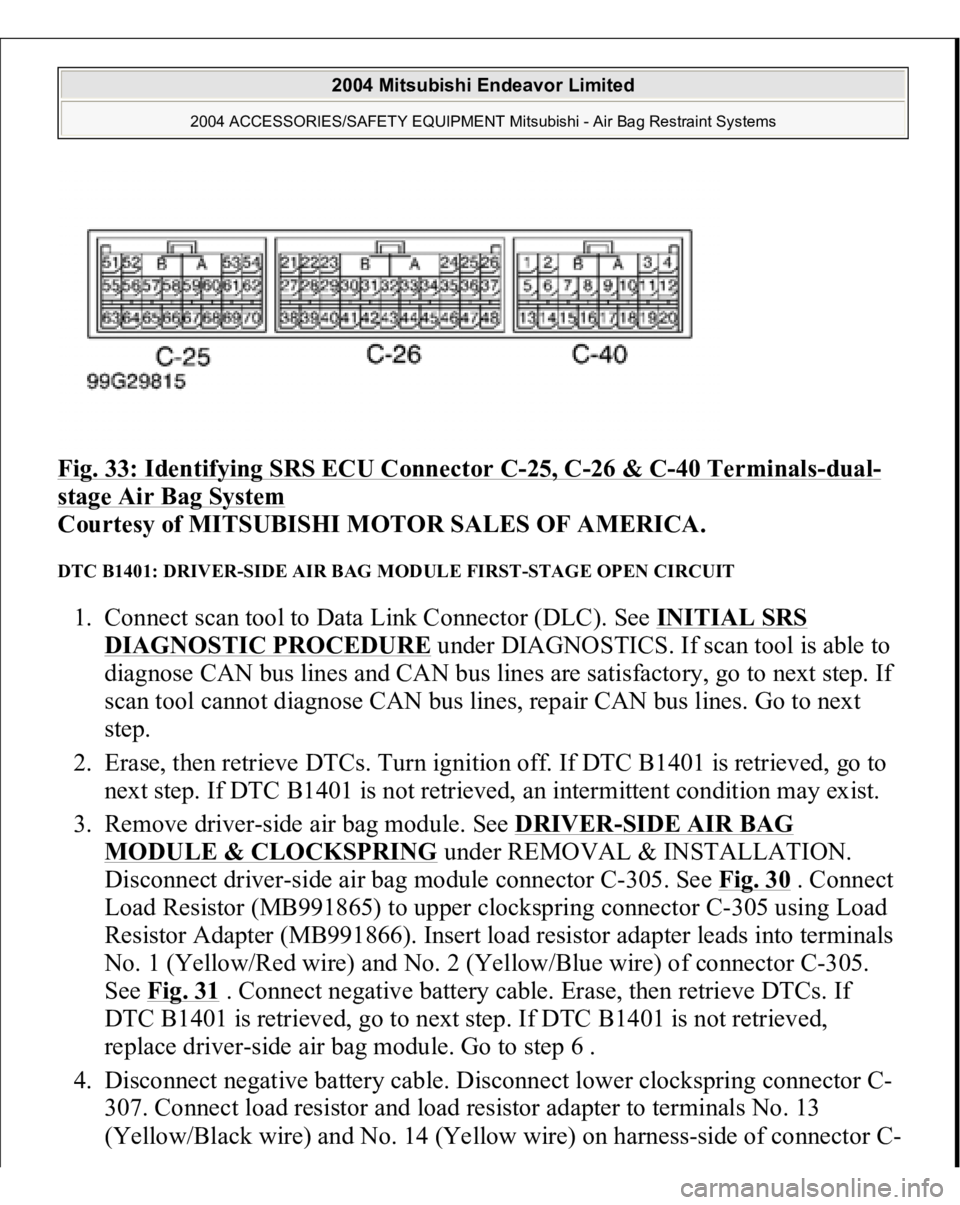
Fig. 33: Identifying SRS ECU Connector C
-25, C
-26 & C
-40 Terminals
-dual
-
stage Air Bag System
Courtesy of MITSUBISHI MOTOR SALES OF AMERICA.
DTC B1401: DRIVER-SIDE AIR BAG MODULE FIRST-STAGE OPEN CIRCUIT 1. Connect scan tool to Data Link Connector (DLC). See INITIAL SRS
DIAGNOSTIC PROCEDURE
under DIAGNOSTICS. If scan tool is able to
diagnose CAN bus lines and CAN bus lines are satisfactory, go to next step. If
scan tool cannot diagnose CAN bus lines, repair CAN bus lines. Go to next
step.
2. Erase, then retrieve DTCs. Turn ignition off. If DTC B1401 is retrieved, go to
next step. If DTC B1401 is not retrieved, an intermittent condition may exist.
3. Remove driver-side air bag module. See DRIVER
-SIDE AIR BAG
MODULE & CLOCKSPRING
under REMOVAL & INSTALLATION.
Disconnect driver-side air bag module connector C-305. See Fig. 30
. Connect
Load Resistor (MB991865) to upper clockspring connector C-305 using Load
Resistor Adapter (MB991866). Insert load resistor adapter leads into terminals
No. 1 (Yellow/Red wire) and No. 2 (Yellow/Blue wire) of connector C-305.
See Fig. 31
. Connect negative battery cable. Erase, then retrieve DTCs. If
DTC B1401 is retrieved, go to next step. If DTC B1401 is not retrieved,
replace driver-side air bag module. Go to step 6 .
4. Disconnect negative battery cable. Disconnect lower clockspring connector C-
307. Connect load resistor and load resistor adapter to terminals No. 13
(Yellow/Black wire
) and No. 14
(Yellow wire
) on ha
rnes
s-side of connector
C-
2004 Mitsubishi Endeavor Limited
2004 ACCESSORIES/SAFETY EQUIPMENT Mitsubishi - Air Bag Restraint Systems