Page 739 of 3870
Fig. 24: Connecting Pressure Gauges To Output Port Of Master Cylinder And Proportioning Valve
Courtesy of MITSUBISHI MOTOR SALES OF AMERICA.
2. Bleed the brake line and the pressure gauges (Refer to PROPORTIONING
VALVE FUNCTION TEST < Vehicles without ABS>
).
3. Depress the brake pedal gradually. Then check that the split point, where the
output fluid pressure begins to drop in proportion to the output fluid pressure,
is at the standard value.
Standard value: 3.19 - 3.67 MPa (463 - 532 psi)
4. Depress the brake pedal more strongly than at the above step. Then check that
the output fluid pressure is at the standard value when the input fluid pressure
is 7.35 MPa (1,066 psi).
Standard value: 4.17 - 4.66 MPa (605 - 676 psi)
5. Measure each out
put fluid
pressure at both valves
, and check that the
2004 Mitsubishi Endeavor LS
2004 BRAKES Basic Brake System - Endeavor
Page 1094 of 3870
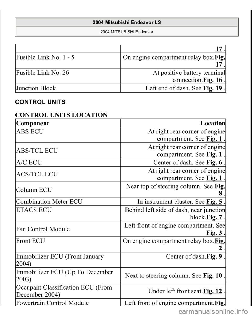
CONTROL UNITS CONTROL UNITS LOCATION
17 .
Fusible Link No. 1 - 5
On engine compartment relay box.Fi
g.
17 .
Fusible Link No. 26
At positive battery terminal
connection.Fig. 16
.
Junction Block
Left end of dash. See Fig. 19
.
Component
Location
ABS ECU
At right rear corner of engine
compartment. See Fig. 1
.
ABS/TCL ECU
At right rear corner of engine
compartment. See Fig. 1
.
A/C ECU
Center of dash. See Fig. 6
.
ACS/TCL ECU
At right rear corner of engine
compartment. See Fig. 1
.
Column ECU
Near top of steering column. See Fi
g. 8 .
Combination Meter ECU
In instrument cluster. See Fig. 5
.
ETACS ECU
Behind left side of dash, near junction
block.Fig. 7
.
Fan Control Module
Left front of engine compartment. See
Fig. 3
.
Front ECU
On engine compartment relay box.Fi
g. 2 .
Immobilizer ECU (From January
2004)
Center of dash.Fig. 9
.
Immobilizer ECU (Up To December
2003)
Next to steering column. See Fig. 10
.
Occupant Classification ECU (From
December 2004)
Under left front seat.Fig. 12
.
Powertrain Control Modul
e
Left front of en
gine com
partment.Fi
g.
2004 Mitsubishi Endeavor LS
2004 MITSUBISHI Endeavor
Page 1095 of 3870
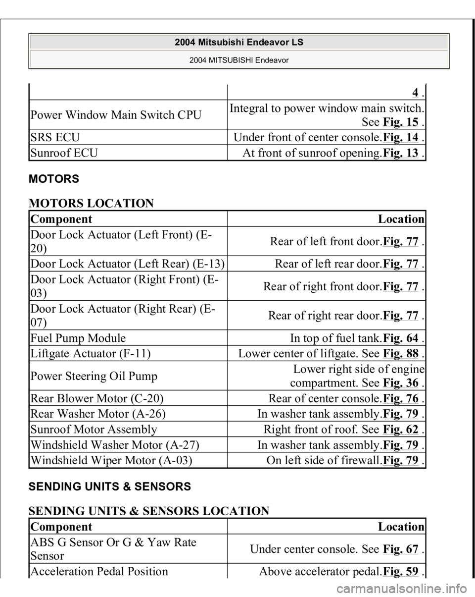
MOTORS MOTORS LOCATION SENDING UNITS & SENSORS SENDING UNITS & SENSORS LOCATION
4 .
Power Window Main Switch CPU
Integral to power window main switch.
See Fig. 15
.
SRS ECU
Under front of center console.Fig. 14
.
Sunroof ECU
At front of sunroof opening.Fig. 13
.
Component
Location
Door Lock Actuator (Left Front) (E-
20)
Rear of left front door.Fig. 77
.
Door Lock Actuator (Left Rear) (E-13)
Rear of left rear door.Fig. 77
.
Door Lock Actuator (Right Front) (E-
03)
Rear of right front door.Fig. 77
.
Door Lock Actuator (Right Rear) (E-
07)
Rear of right rear door.Fig. 77
.
Fuel Pump Module
In top of fuel tank.Fig. 64
.
Liftgate Actuator (F-11)
Lower center of liftgate. See Fig. 88
.
Power Steering Oil Pump
Lower right side of engine
compartment. See Fig. 36
.
Rear Blower Motor (C-20)
Rear of center console.Fig. 76
.
Rear Washer Motor (A-26)
In washer tank assembly.Fig. 79
.
Sunroof Motor Assembly
Right front of roof. See Fig. 62
.
Windshield Washer Motor (A-27)
In washer tank assembly.Fig. 79
.
Windshield Wiper Motor (A-03)
On left side of firewall.Fig. 79
.
Component
Location
ABS G Sensor Or G & Yaw Rate
Sensor
Under center console. See Fig. 67
.
Acceleration Pedal Position
Above accelerator pedal.Fig. 59
.
2004 Mitsubishi Endeavor LS
2004 MITSUBISHI Endeavor
Page 1096 of 3870
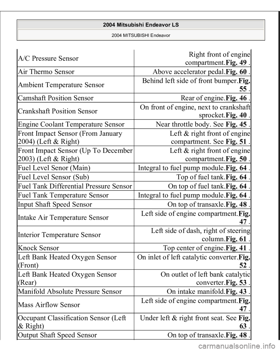
A/C Pressure Sensor
Right front of engine
compartment.Fig. 49
.
Air Thermo Sensor
Above accelerator pedal.Fig. 60
.
Ambient Temperature Sensor
Behind left side of front bumper.Fig.
55 .
Camshaft Position Sensor
Rear of engine.Fig. 46
.
Crankshaft Position Sensor
On front of engine, next to crankshaft
sprocket.Fig. 40
.
Engine Coolant Temperature Sensor
Near throttle body. See Fig. 45
.
Front Impact Sensor (From January
2004) (Left & Right)
Left & right front of engine
compartment. See Fig. 51
.
Front Impact Sensor (Up To December
2003) (Left & Right)
Left & right front of engine
compartment.Fig. 50
.
Fuel Level Senor (Main)
Integral to fuel pump module.Fig. 64
.
Fuel Level Sensor (Sub)
Top of fuel tank.Fig. 64
.
Fuel Tank Differential Pressure Sensor
On top of fuel tank.Fig. 64
.
Fuel Tank Temperature Sensor
Integral to fuel pump module.Fig. 64
.
Input Shaft Speed Sensor
On top of transaxle.Fig. 48
.
Intake Air Temperature Sensor
Left side of engine compartment.Fi
g.
47 .
Interior Temperature Sensor
Left side of dash, right of steering
column.Fig. 61
.
Knock Sensor
Top center of engine.Fig. 41
.
Left Bank Heated Oxygen Sensor
(Front)
On inlet of left catalytic converter.Fi
g.
52 .
Left Bank Heated Oxygen Sensor
(Rear)
On outlet of left bank catalytic
converter.Fig. 53
.
Manifold Absolute Pressure Sensor
On intake manifold.Fig. 43
.
Mass Airflow Sensor
Left side of engine compartment.Fi
g.
47 .
Occupant Classification Sensor (Left
& Right)
Under left & right front seat. See Fi
g.
63 .
Output Shaft Speed Sensor
On top of transaxle.Fig. 48
.
2004 Mitsubishi Endeavor LS
2004 MITSUBISHI Endeavor
Page 1097 of 3870
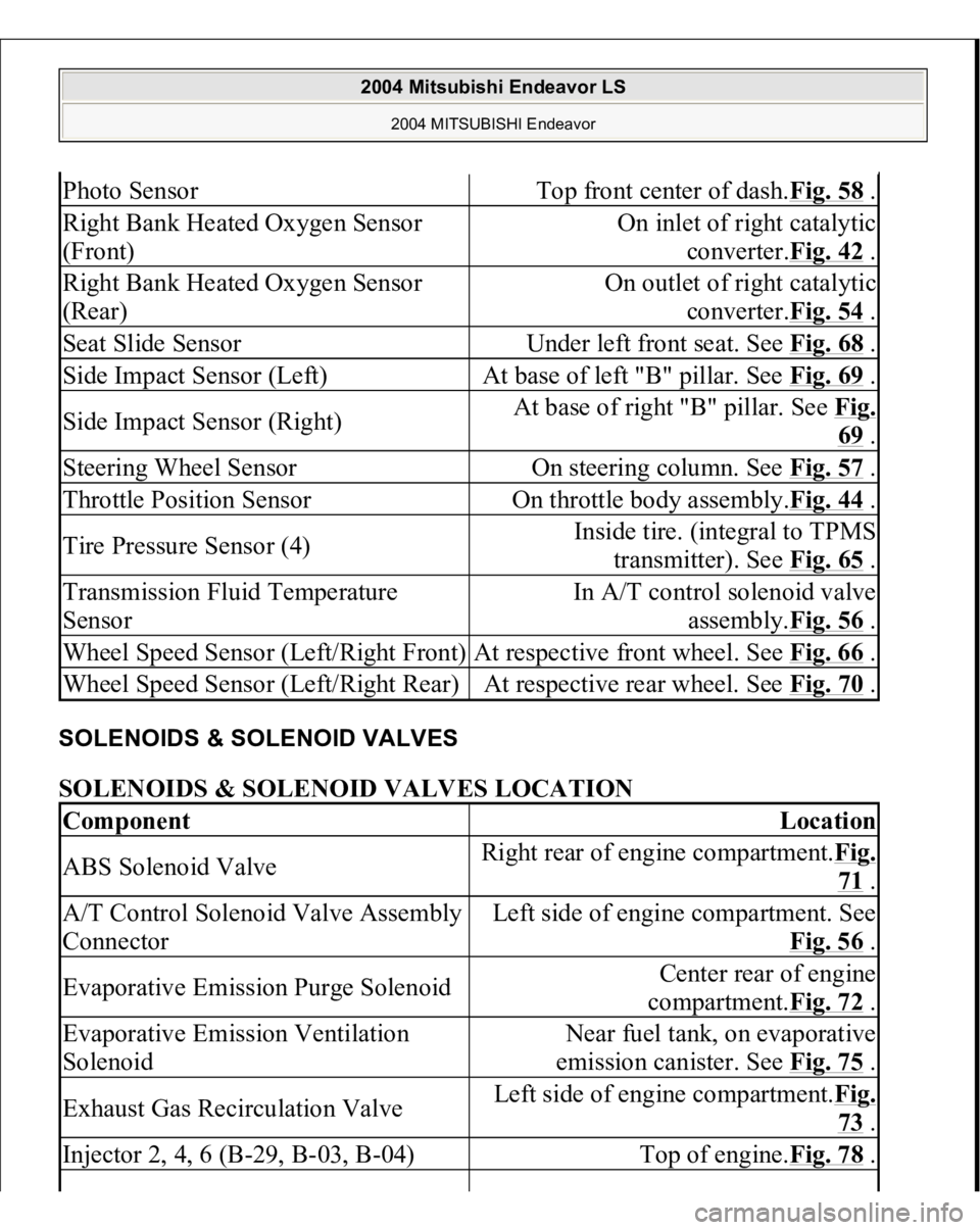
SOLENOIDS & SOLENOID VALVES SOLENOIDS & SOLENOID VALVES LOCATION Photo Sensor
Top front center of dash.Fig. 58
.
Right Bank Heated Oxygen Sensor
(Front)
On inlet of right catalytic
converter.Fig. 42
.
Right Bank Heated Oxygen Sensor
(Rear)
On outlet of right catalytic
converter.Fig. 54
.
Seat Slide Sensor
Under left front seat. See Fig. 68
.
Side Impact Sensor (Left)
At base of left "B" pillar. See Fig. 69
.
Side Impact Sensor (Right)
At base of right "B" pillar. See Fig.
69 .
Steering Wheel Sensor
On steering column. See Fig. 57
.
Throttle Position Sensor
On throttle body assembly.Fig. 44
.
Tire Pressure Sensor (4)
Inside tire. (integral to TPMS
transmitter). See Fig. 65
.
Transmission Fluid Temperature
Sensor
In A/T control solenoid valve
assembly.Fig. 56
.
Wheel Speed Sensor (Left/Right Front)
At respective front wheel. See Fig. 66
.
Wheel Speed Sensor (Left/Right Rear)
At respective rear wheel. See Fig. 70
.
Component
Location
ABS Solenoid Valve
Right rear of engine compartment.Fig.
71 .
A/T Control Solenoid Valve Assembly
Connector
Left side of engine compartment. See
Fig. 56
.
Evaporative Emission Purge Solenoid
Center rear of engine
compartment.Fig. 72
.
Evaporative Emission Ventilation
Solenoid
Near fuel tank, on evaporative
emission canister. See Fig. 75
.
Exhaust Gas Recirculation Valve
Left side of engine compartment.Fig.
73 .
Injector 2, 4, 6 (B-29, B-03, B-04)
Top of engine.Fig. 78
.
2004 Mitsubishi Endeavor LS
2004 MITSUBISHI Endeavor
Page 1188 of 3870
2004 ENGINE
Engine Cooling - Endeavor
GENERAL DESCRIPTION The cooling system is designed to keep every part of the engine at appropriate
temperature in whatever condition the engine may be operated. The cooling method
is of the water-cooled, pressure forced circulation type in which the water pump
pressurizes coolant and circulates it throughout the engine. If the coolant
temperature exceeds the prescribed temperature, the thermostat opens to circulate
the coolant through the radiator as well so that the heat absorbed by the coolant may
be radiated into the air. The water pump is of the centrifugal type and is driven by
the drive belt from the crankshaft. The radiator is the corrugated fin, down flow
type. CONSTRUCTION DIAGRAM Fig. 1: Identifying Engine Cooling Construction Diagram
2004 Mitsubishi Endeavor Limited 2004 ENGINE Engine Cooling - Endeavor
2004 Mitsubishi Endeavor Limited 2004 ENGINE Engine Cooling - Endeavor
Page 1255 of 3870
Fig. 51: Disconnecting Radiator Lower Hose
Courtesy of MITSUBISHI MOTOR SALES OF AMERICA.
INSTALLATION SERVICE POINTS > >A<< THERMOSTAT INSTALLATION Install the thermostat so that the jiggle valve is facing straight up. Be careful not to
fold or scratch the rubber rin
g.
CAUTION: Make absolutely sure that no oil adheres to the
rubber ring of the thermostat. Also do not fold or
scratch the rubber ring during installation.
2004 Mitsubishi Endeavor Limited 2004 ENGINE Engine Cooling - Endeavor
Page 1786 of 3870
Fig. 143: Identifying Connector C
-105,C
-110,C
-113
Courtesy of MITSUBISHI MOTOR SALES OF AMERICA.
Q: Are radio and CD player connector C-105 or radio, CD player and CD
changer connector C-105, C-110, C-113 and amplifier connector C-11, C-
12 in good condition?
YES: Go to Step 4.
NO: Repair or replace the damaged component(s). Check that there is no
noise.
STEP 4. Check that noise appears when the radio switch is turned on
while the vehicle is sto
pp
ed and the radio is ta
pp
ed while tuned awa
y from
a station.
Q: Does noise appear when the radio switch is turned on while the vehicle
is stopped and the radio is tapped while tuned away from a station?
YES: Go to Step 5.
NO: It may be static electricity noise.
STEP 5. Verify that the radio is correctly grounded.
The radio is connected to the ground with an assembling screw.
Q: Is the radio correctly grounded?
YES: Go to Step 6.
NO: Tighten the screw securely. Check that there is no noise.
STEP 6. Check by replacing radio and CD player.
NOTE: Body static electricity from the shock absorber rubber
bushings used to prevent vibration, tires, etc. occurs
because of separation from the ground, causing a
buzzing noise. Since no measures can be taken to
discharge the static electricity of the vehicle body.
Check that there is no noise.
2004 Mitsubishi Endeavor LS
2004 BODY & ACCESSORIES Radio With Tape Player & Cd Player - Endeavor