Page 888 of 3870
2. Turn the ignition switch to the "ON" position.
3. Set scan tool MB991958 to data reading mode for auto-cruise control
system.
Item 06, Brake Switch.
When the brake pedal is depressed, the display on scan tool
MB991958 should be "OFF". When the brake pedal is released, the display on scan tool
MB991958 should be "ON".
4. Turn the ignition switch to the "LOCK" (OFF) position.
5. Disconnect scan tool MB991958.
Q: Is the switch operating properly?
YES : Go to Step 21 .
NO : Go to Step 15 .
STEP 3. Check the stoplight operation.
Check the stoplight operation.
When the brake pedal is depressed, the stoplight will illuminate. When the brake pedal is released, the stoplight does not illuminate.
Q: Is the stoplight will illuminate (when the brake pedal is depressed) and
the stoplight does not illuminate (when the brake pedal is released)?
YES : Go to Step 4.
NO : Go to Step 8 .
STEP 4. Measure the terminal voltage at PCM connector B-18.
1. Disconnect all the connectors from the PCM.
2004 Mitsubishi Endeavor LS
2004 BODY & ACCESSORIES Auto, Cruise Control System - Endeavor
Page 902 of 3870
5. Turn the ignition switch to the "LOCK" (OFF) position.
Q: Is the measured voltage battery positive voltage (approximately 12
volts) when the brake pedal is depressed and 1 volt or less when the brake
pedal is released?
YES : It can be assumed that this malfunction is intermittent. (Refer to
HOW TO COPE WITH INTERMITTENT MALFUNCTIONS
).
Then go to Step 22 .
NO : Replace the PCM. [Refer to POWERTRAIN CONTROL
MODULE (PCM)
]. Then go to Step 22 .
STEP 8. Measure the power supply voltage at stoplight switch connector
C-03 by backprobing.
1. Do not disconnect stoplight switch connector C-03.
2004 Mitsubishi Endeavor LS
2004 BODY & ACCESSORIES Auto, Cruise Control System - Endeavor
Page 903 of 3870
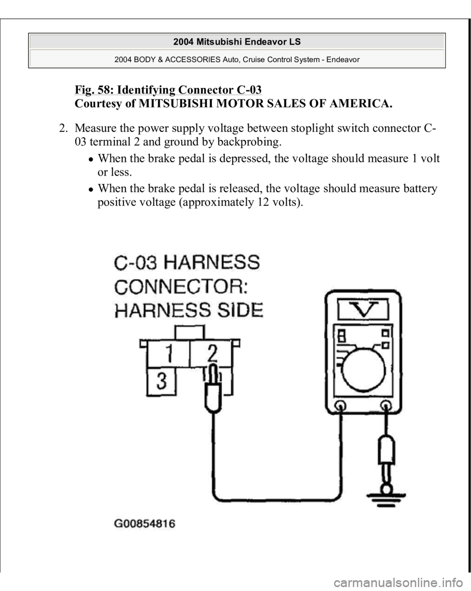
Fig. 58: Identifying Connector C
-03
Courtesy of MITSUBISHI MOTOR SALES OF AMERICA.
2. Measure the power supply voltage between stoplight switch connector C-
03 terminal 2 and ground by backprobing.
When the brake pedal is depressed, the voltage should measure 1 volt
or less. When the brake pedal is released, the voltage should measure battery
positive voltage (approximately 12 volts).
2004 Mitsubishi Endeavor LS
2004 BODY & ACCESSORIES Auto, Cruise Control System - Endeavor
Page 904 of 3870
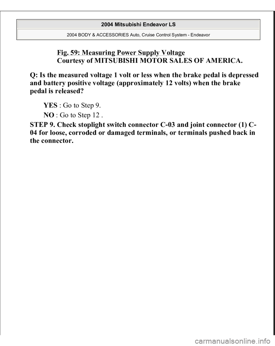
Fig. 59: Measuring Power Supply Voltage
Courtesy of MITSUBISHI MOTOR SALES OF AMERICA.
Q: Is the measured volta
ge 1 volt or less when the brake
pedal is de
pressed
and battery positive voltage (approximately 12 volts) when the brake
pedal is released?
YES : Go to Step 9.
NO : Go to Step 12 .
STEP 9. Check stoplight switch connector C-03 and joint connector (1) C-
04 for loose, corroded or damaged terminals, or terminals pushed back in
the connector.
2004 Mitsubishi Endeavor LS
2004 BODY & ACCESSORIES Auto, Cruise Control System - Endeavor
Page 908 of 3870
Courtesy of MITSUBISHI MOTOR SALES OF AMERICA
.
Q: Is the harness wire in good condition?
YES : Go to Step 11.
NO : Repair the damaged harness wire. Then go to Step 22 .
STEP 11. Check the stoplight switch.
1. Remove the stoplight switch. (Refer to BRAKE PEDAL
).
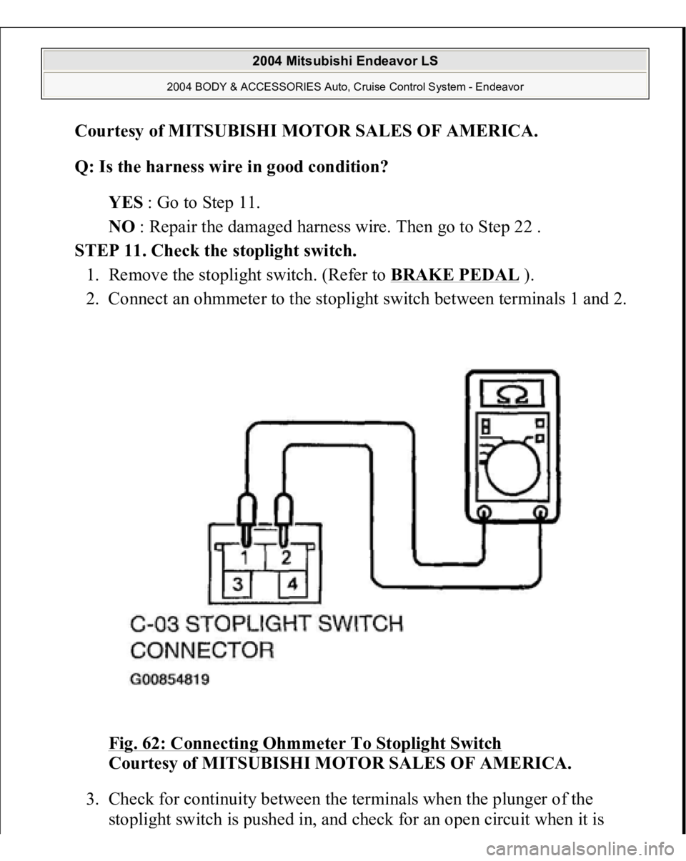
2. Connect an ohmmeter to the stoplight switch between terminals 1 and 2.
Fig. 62: Connecting Ohmmeter To Stoplight Switch
Courtesy of MITSUBISHI MOTOR SALES OF AMERICA.
3. Check for continuity between the terminals when the plunger of the
sto
plight switch is
pushed in, and check for an o
pen circuit when it is
2004 Mitsubishi Endeavor LS
2004 BODY & ACCESSORIES Auto, Cruise Control System - Endeavor
Page 909 of 3870
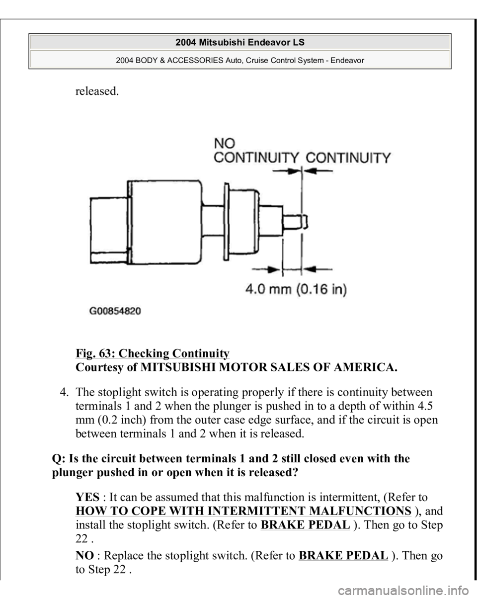
released.
Fig. 63: Checking Continuity
Courtesy of MITSUBISHI MOTOR SALES OF AMERICA.
4. The stoplight switch is operating properly if there is continuity between
terminals 1 and 2 when the plunger is pushed in to a depth of within 4.5
mm (0.2 inch) from the outer case edge surface, and if the circuit is open
between terminals 1 and 2 when it is released.
Q: Is the circuit between terminals 1 and 2 still closed even with the
plunger pushed in or open when it is released?
YES : It can be assumed that this malfunction is intermittent, (Refer to
HOW TO COPE WITH INTERMITTENT MALFUNCTIONS
), and
install the stoplight switch. (Refer to BRAKE PEDAL
). Then go to Step
22 .
NO : Replace the stoplight switch. (Refer to BRAKE PEDAL
). Then go
to Step 2
2 .
2004 Mitsubishi Endeavor LS
2004 BODY & ACCESSORIES Auto, Cruise Control System - Endeavor
Page 917 of 3870
Fig. 69: Measuring Terminal Voltage Between Special Tool 23
-
Pin Connector Terminal 33 And Ground
Courtesy of MITSUBISHI MOTOR SALES OF AMERICA.
5. Turn the ignition switch to the "LOCK" (OFF) position.
Q: Is the measured voltage battery positive voltage (approximately 12
volts) when the brake pedal is depressed and 1 volt or less when the brake
pedal is released?
YES : Go to Step 21 .
NO : Go to Step 16.
STEP 16. Check PCM connector B-19 and stoplight switch connector C-03
for loose, corroded or dama
ged terminals, or terminals
pushed back in the
connector.
2004 Mitsubishi Endeavor LS
2004 BODY & ACCESSORIES Auto, Cruise Control System - Endeavor
Page 922 of 3870
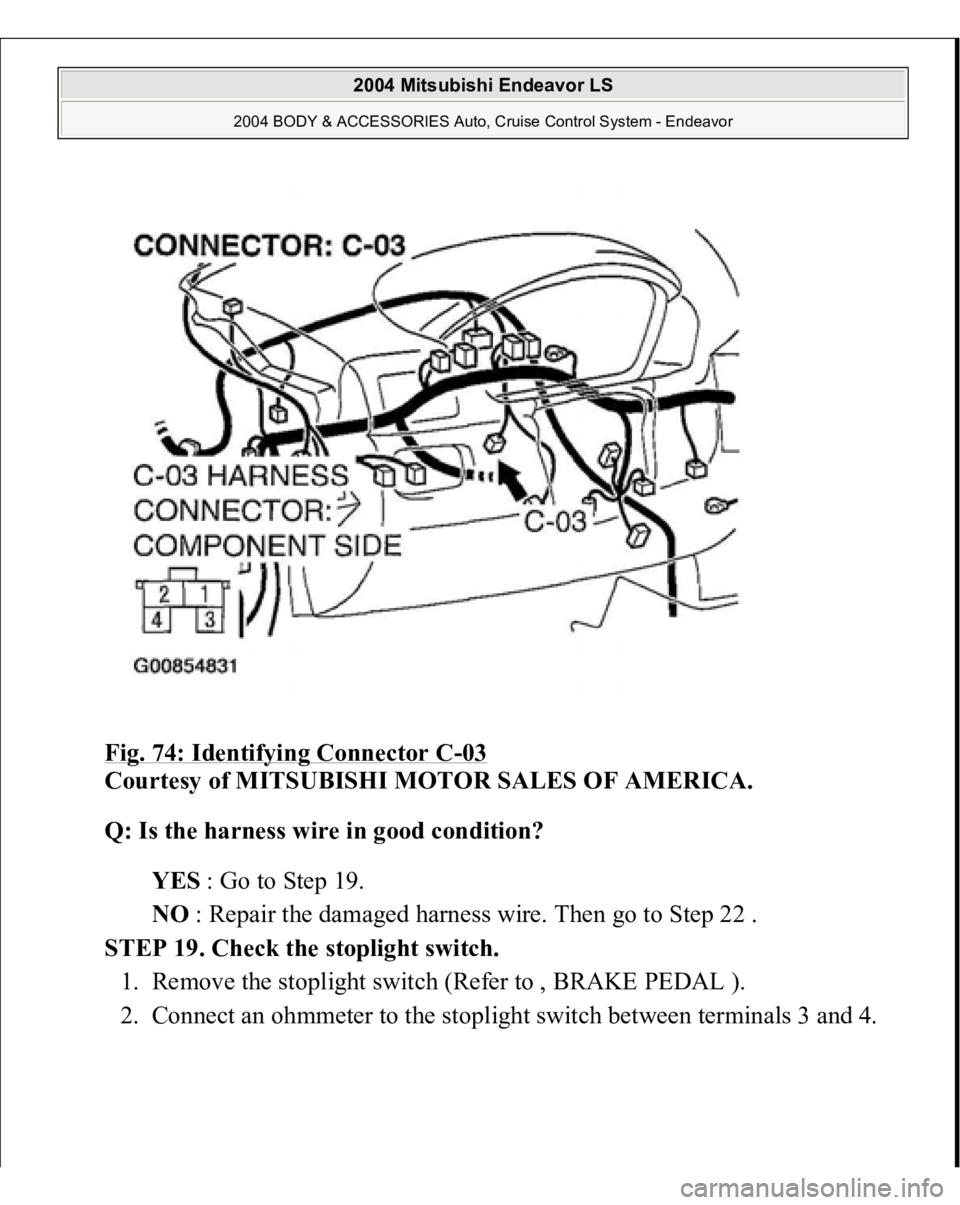
Fig. 74: Identifying Connector C
-03
Courtesy of MITSUBISHI MOTOR SALES OF AMERICA.
Q: Is the harness wire in good condition?
YES : Go to Step 19.
NO : Repair the damaged harness wire. Then go to Step 22 .
STEP 19. Check the stoplight switch.
1. Remove the stoplight switch (Refer to , BRAKE PEDAL ).
2. Connect an ohmmeter to the stoplight switch between terminals 3 and 4.
2004 Mitsubishi Endeavor LS
2004 BODY & ACCESSORIES Auto, Cruise Control System - Endeavor