Page 810 of 3870
11. Remove condenser fan motor.
12. To install, reverse removal procedures.
Fig. 13: Exploded View Of Radiator & Radiator Fans
Courtesy of MITSUBISHI MOTOR SALES OF AMERICA.
WIRING DIAGRAMS See COOLING FAN in appropriate SYSTEM WIRING DIAGRAMS article in
ELECTRICAL.
2004 Mitsubishi Endeavor Limited
2004 ENGINE COOLING Electric Cooling Fans - Endeavor
Page 1188 of 3870
2004 ENGINE
Engine Cooling - Endeavor
GENERAL DESCRIPTION The cooling system is designed to keep every part of the engine at appropriate
temperature in whatever condition the engine may be operated. The cooling method
is of the water-cooled, pressure forced circulation type in which the water pump
pressurizes coolant and circulates it throughout the engine. If the coolant
temperature exceeds the prescribed temperature, the thermostat opens to circulate
the coolant through the radiator as well so that the heat absorbed by the coolant may
be radiated into the air. The water pump is of the centrifugal type and is driven by
the drive belt from the crankshaft. The radiator is the corrugated fin, down flow
type. CONSTRUCTION DIAGRAM Fig. 1: Identifying Engine Cooling Construction Diagram
2004 Mitsubishi Endeavor Limited 2004 ENGINE Engine Cooling - Endeavor
2004 Mitsubishi Endeavor Limited 2004 ENGINE Engine Cooling - Endeavor
Page 1196 of 3870
Fig. 5: Radiator Fan and Condenser Fan Drive Circuit Diagram & Connector Identification
Courtesy of MITSUBISHI MOTOR SALES OF AMERICA.
2004 Mitsubishi Endeavor Limited 2004 ENGINE Engine Cooling - Endeavor
Page 2519 of 3870

By operating two ignition keys that have been already registered (Refer to ON
-
VEHICLE SERVICE
).
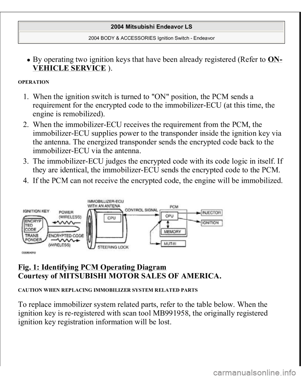
OPERATION 1. When the ignition switch is turned to "ON" position, the PCM sends a
requirement for the encrypted code to the immobilizer-ECU (at this time, the
engine is remobilized).
2. When the immobilizer-ECU receives the requirement from the PCM, the
immobilizer-ECU supplies power to the transponder inside the ignition key via
the antenna. The energized transponder sends the encrypted code back to the
immobilizer-ECU via the antenna.
3. The immobilizer-ECU judges the encrypted code with its code logic in itself. If
they are identical, the immobilizer-ECU sends the encrypted code to the PCM.
4. If the PCM can not receive the encrypted code, the engine will be immobilized.
Fig. 1: Identifying PCM Operating Diagram
Courtesy of MITSUBISHI MOTOR SALES OF AMERICA.
CAUTION WHEN REPLACING IMMOBILIZER SYSTEM RELATED PARTS To replace immobilizer system related parts, refer to the table below. When the
ignition key is re-registered with scan tool MB991958, the originally registered
ignition key registration information will be lost.
2004 Mitsubishi Endeavor LS
2004 BODY & ACCESSORIES Ignition Switch - Endeavor
Page 2521 of 3870

means of a forged key or by connecting the ignition wiring directly. The system is
significantly safe and reliable against theft. In addition, the driver has only to turn
the ignition switch to the "ON" position to activate the immobilizer system. If the
requirements for starting the engine are not satisfied, the engine will be
immobilized. If a registered ignition key is lost, all your ignition keys need to be
registered again using scan tool MB991958 (MUT-III Sub Assembly) to ensure
security (Refer to ON
-VEHICLE SERVICE
). An additional ignition key can be
registered as follows (only if no ignition keys are lost):
Using scan tool MB991958 (MUT-III Sub Assembly) (Refer to ON
-
VEHICLE SERVICE
).
By operating two ignition keys that have been already registered (Refer toON
-
VEHICLE SERVICE
).
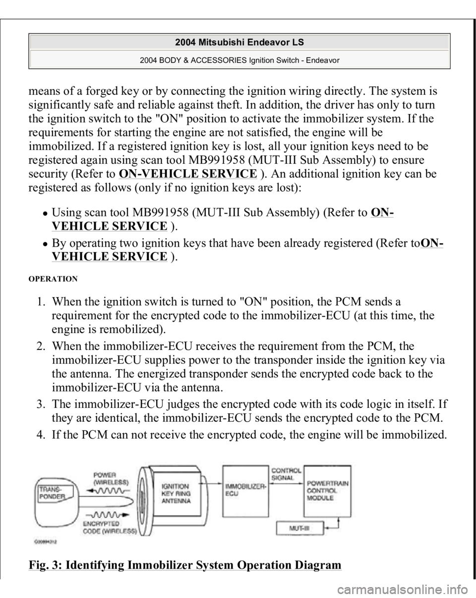
OPERATION 1. When the ignition switch is turned to "ON" position, the PCM sends a
requirement for the encrypted code to the immobilizer-ECU (at this time, the
engine is remobilized).
2. When the immobilizer-ECU receives the requirement from the PCM, the
immobilizer-ECU supplies power to the transponder inside the ignition key via
the antenna. The energized transponder sends the encrypted code back to the
immobilizer-ECU via the antenna.
3. The immobilizer-ECU judges the encrypted code with its code logic in itself. If
they are identical, the immobilizer-ECU sends the encrypted code to the PCM.
4. If the PCM can not receive the encrypted code, the engine will be immobilized.
Fig. 3: Identifying Immobilizer System Operation Diagram
2004 Mitsubishi Endeavor LS
2004 BODY & ACCESSORIES Ignition Switch - Endeavor
Page 2624 of 3870
Fig. 81: Immobilizer Indicator Light Circuit Diagram & Connector Identification
Courtesy of MITSUBISHI MOTOR SALES OF AMERICA.
CIRCUIT OPERATION If the requirements for starting the engine are not satisfied, the immobilizer-ECU
flashes the immobilizer indicator for 30 seconds.
2004 Mitsubishi Endeavor LS
2004 BODY & ACCESSORIES Ignition Switch - Endeavor
Page 2684 of 3870
Fig. 1: Ignition System Circuit Diagram
Courtesy of MITSUBISHI MOTOR SALES OF AMERICA.
SPECIAL TOOLS Fig. 2: Identifying Special Tool
Courtesy of MITSUBISHI MOTOR SALES OF AMERICA.
ON-VEHICLE SERVICE KNOCK CONTROL SYSTEM CHECK Check the knock sensor circuit if diagnostic trouble code, No. P0325 is shown.
Refer to DTC P0325: KNOCK SENSOR CIRCUIT MALFUNCTION
.
2004 Mitsubishi Endeavor Limited 2004 ENGINE Ignition System - Endeavor
Page 3121 of 3870
unit reservoir, will be supplied to the front left wheel during oversteering or the rear
right wheel during understeering when the vehicle is at right turn. Furthermore, the
system also controls the engine if the accelerator pedal is depressed excessively. DURING NORMAL BRAKING Fig. 11: During Normal Braking Diagram
Courtesy of MITSUBISHI MOTOR SALES OF AMERICA.
The brake fluid flows from the master cylinder to the cut valve and the inlet valve
to supply fluid pressure to the relevant wheels.
2004 Mitsubishi Endeavor LS
2004 BRAKES Traction Control, Active Skid Control System - Endeavor