Page 159 of 344

159 Controls in detail
Loading
Hooks
Four hooks located on the rear compart-
ment trim panels, two on each side.HooksUse the hooks to secure light weight items.
The maximum permissible weight per hook
is 9 lbs (4 kg).
Partition net*Use of the partition net is a particularly im-
portant safety factor when the vehicle is
loaded higher than the top of the seat
backrests with smaller objects.
The partition net can be installed behind
the backrests of the front or rear seats.
Engaging partition net
1Holder
2Mounting hookWarning!
G
Always lock backrest in its upright position
when rear seat bench is occupied by pas-
sengers, or cargo is being carried behind the
seat bench.
To help avoid personal injury from smaller
objects flying in the occupant area during a
collision or sudden maneuver, always use
partition net when transporting cargo.
The partition net cannot prevent the move-
ment of large, heavier objects into the pas-
senger area in an accident. Such items must
be properly secured using the cargo
tie-down rings in the cargo area floor
(�page 158).
Passenger use of seats behind installed par-
tition net is restricted because of the foot-
well being taken up by the net.
Page 163 of 344
163 Controls in detail
Loading
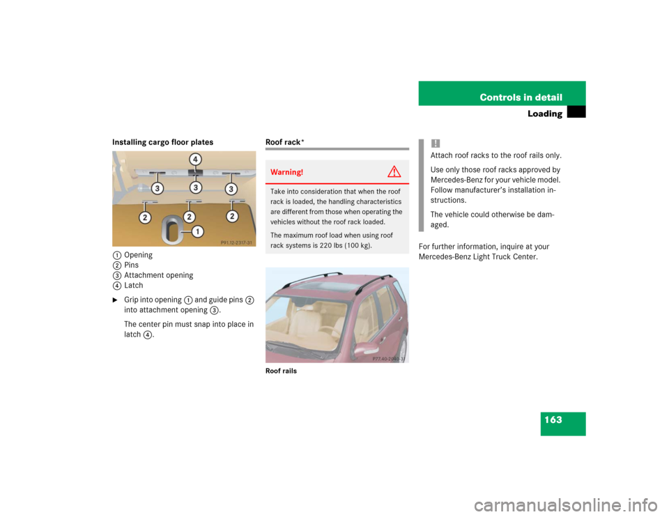
Installing cargo floor plates
1Opening
2Pins
3Attachment opening
4Latch�
Grip into opening1 and guide pins2
into attachment opening3.
The center pin must snap into place in
latch4.
Roof rack*Roof rails
For further information, inquire at your
Mercedes-Benz Light Truck Center.
Warning!
G
Take into consideration that when the roof
rack is loaded, the handling characteristics
are different from those when operating the
vehicles without the roof rack loaded.
The maximum roof load when using roof
rack systems is 220 lbs (100 kg).
!Attach roof racks to the roof rails only.
Use only those roof racks approved by
Mercedes-Benz for your vehicle model.
Follow manufacturer’s installation in-
structions.
The vehicle could otherwise be dam-
aged.
Page 168 of 344

168 Controls in detailUseful featuresAshtrays and cigarette lighter Ashtray and cigarette lighter in the
front center console
1Ashtray
2Cigarette lighter
3Cover plate
Opening the ashtray
�
Briefly touch cover plate3.
The ashtray opens automatically.Removing ashtray insert
�
Secure vehicle from movement by set-
ting the parking brake. Move the gear
selector lever to positionN.
Now you have more room to take out
the insert.
�
Grip the insert on the sides and pull it
out upwards.
Reinstalling ashtray insert
�
Install ashtray insert.
�
Close the ashtray.
Warning!
G
Never touch the heating element or sides of
the cigarette lighter; they are extremely hot.
Hold the knob only.
When leaving the vehicle always remove the
key from the steering lock. Do not leave chil-
dren unattended in the vehicle, or with ac-
cess to an unlocked vehicle. Unsupervised
use of vehicle equipment may cause an ac-
cident and / or serious personal injury.iThe cigarette lighter socket can be
used to accommodate electrical acces-
sories up to a maximum of 50 W.
If the engine is off, the battery may be-
come discharged when used for long
periods of time.
Warning!
G
Remove ashtray only with vehicle standing
still. Set the parking brake to secure vehicle
from movement. Move gear selector lever to
positionN. With gear selector lever in
positionN, turn off the engine.
Page 169 of 344
169 Controls in detail
Useful features
Cigarette lighter�
Switch on the ignition.
�
Push in cigarette lighter2
(�page 168).
The cigarette lighter will pop out auto-
matically when hot.
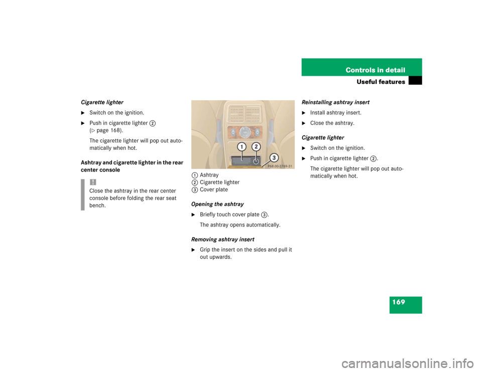
Ashtray and cigarette lighter in the rear
center console
1Ashtray
2Cigarette lighter
3Cover plate
Opening the ashtray
�
Briefly touch cover plate3.
The ashtray opens automatically.
Removing ashtray insert
�
Grip the insert on the sides and pull it
out upwards.Reinstalling ashtray insert
�
Install ashtray insert.
�
Close the ashtray.
Cigarette lighter
�
Switch on the ignition.
�
Push in cigarette lighter2.
The cigarette lighter will pop out auto-
matically when hot.
!Close the ashtray in the rear center
console before folding the rear seat
bench.
Page 170 of 344

170 Controls in detailUseful featuresElectrical outletElectrical outletOne outlet is located in the front passen-
ger footwell and another on the right-hand
side of the luggage compartment.�
Flip up cover and insert electrical plug
(cigarette lighter type).
Telephone*
Radio transmitters, such as a portable tele-
phone or a citizens band unit, should only
be used inside the vehicle if they are con-
nected to an antenna that is installed on
the outside of the vehicle.
The external antenna must be approved by
Mercedes-Benz. Please contact an autho-
rized Mercedes-Benz Light Truck Center
for information on the installation of an ap-
proved external antenna. Refer to the radio
transmitter operation instructions regard-
ing use of an external antenna.
iThe outlets function even if the key is
not in the ignition.
The electrical outlet can be used to
accommodate electrical consumers
(e.g. air pump, auxiliary lamps) up to a
maximum of 180 W.
If the engine is off, the battery may be-
come discharged if used for long peri-
ods of time.
Warning!
G
Never operate radio transmitters equipped
with a built-in or attached antenna (i.e. with-
out being connected to an external antenna)
from inside the vehicle while the engine is
running. Doing so could lead to a malfunc-
tion of the vehicle’s electronic system, pos-
sibly resulting in an accident and / or serious
personal injury.
Page 173 of 344
 or airbags deploy,
�")
173 Controls in detail
Useful features
Emergency calls
An emergency call is initiated automatical-
ly:�
following an accident in which the
emergency tensioning detractors
(ETDs) or airbags deploy,
�
if the anti-theft alarm or the tow-away
alarm stays on for more than
20 seconds. See anti-theft alarm sys-
tem (
�page 83) and tow-away alarm
(
�page 84).
An emergency call can also be initiated
manually by opening the cover next to the
inside rear view mirror labeled SOS, then
briefly pressing the button located under
the cover. See below for instructions on
initiating an emergency call manually.
Warning!
G
The Tele Aid control unit is located under
the front passenger seat. If there is accumu-
lation of water or other liquid in this area,
the Tele Aid control unit could suffer an
electrical short circuit making the system in-
operative. In this case the indicator lamp in
the SOS button will not illuminate during or
will remain illuminated after the system
self-check. Have the system checked at the
nearest Mercedes-Benz Light Truck Center
as soon as possible.
If the indicator lamps in the SOS button, in
the Roadside Assistance button and / or in
the Information button do not come on dur-
ing the system self-check or if any of these
indicators remain illuminated constantly in
red and / or the message
TELE AID -
VISIT WORKSHOP
is displayed in the MCS
display after the system self-check, a mal-
function in the system has been detected.
If a malfunction is indicated as outlined
above, the system may not operate as ex-
pected. Have the system checked at the
nearest Mercedes-Benz Light Truck Center
as soon as possible.
Page 176 of 344

176 Controls in detailUseful featuresWhen the connection is established, the
message
ROADSIDE ASSISTANCE –
CALL CONNECTED
appears in the MCS dis-
play. The Tele Aid system will transmit data
generating the vehicle identification num-
ber, model, color and location (subject to
availability of cellular and GPS signals).
A voice connection between the Roadside
Assistance dispatcher and the occupants
of the vehicle will be established. When a
voice connection is established the audio
system mutes and the message
TELE AID
– ROADSIDE ASSISTANCE CALL ACTIVE
ap-
pears in the MCS display.
�
Describe the nature of the need for as-
sistance.The Mercedes-Benz Roadside assistance
dispatcher will either dispatch a qualified
Mercedes-Benz technician or arrange to
tow your vehicle to the nearest
Mercedes-Benz Light Truck Center. For
services such as labor and / or towing,
charges may apply. Refer to the Roadside
Assistance manual for more information.
These programs are only available in the
USA:
�
Sign and Drive services: Services such
as jump start, a few gallons of fuel or
the replacement of a flat tire with the
vehicle spare tire are obtainable,
�
Remote Vehicle Diagnostics: This func-
tion permits the Mercedes-Benz Road-
side Assistance dispatcher to
download malfunction codes and actu-
al vehicle data.
iWhile the call is connected you can
change to navigation menu by pressing
NAVI button on the MCS unit.
iThe indicator lamp in the Roadside As-
sistance button• remains illumi-
nated in red for approx. ten seconds
during the system self-check after turn-
ing the key in the steering lock to
position2 (together with the SOS but-
ton and the Information button¡).
See system self-check (
�page 172)
when the indicator lamp does not light
up in red or stays on longer than ap-
proximately ten seconds.
Page 177 of 344
.
A ca")
177 Controls in detail
Useful features
Information button¡
1Cover
2Information button¡�
Briefly press on cover1.
The cover will open.
�
Press and hold the button (for longer
than two seconds).
A call to the Customer Assistance Cen-
ter will be initiated. The button will
flash while the call is in progress. The
message
INFO – CONNECTING CALL
will
appear in the MCS display.When the connection is established, the
message
INFO – CALL CONNECTED
appears
in the MCS display. The Tele Aid system
will transmit data generating the vehicle
identification number, model, color and lo-
cation (subject to availability of cellular
and GPS signals).
A voice connection between the Customer
Assistance Center representative and the
occupants of the vehicle will be estab-
lished. When a voice connection is estab-
lished the audio system mutes and the
message
TELE AID – INFO CALL ACTIVE
appears in the MCS display. Information
regarding the operation of your vehicle, the
nearest Mercedes-Benz Light Truck Center
or Mercedes-Benz USA products and ser-
vices is available to you. If the indicator lamp in the Roadside
Assistance button• is illuminated
continuously and there was no voice
connection to the Response Center es-
tablished, then the Tele Aid system
could not initiate a Roadside Assis-
tance call (e.g. the relevant cellular
phone network was not available). The
message
ROADSIDE ASSISTANCE –
CALL FAILED
appears in the MCS dis-
play.
Roadside Assistance calls can be ter-
minated using the END Button on the
MCS unit.
iWhile the call is connected, you can
change to navigation menu by pressing
NAVI button on the MCS unit.