Page 159 of 344

159 Controls in detail
Loading
Hooks
Four hooks located on the rear compart-
ment trim panels, two on each side.HooksUse the hooks to secure light weight items.
The maximum permissible weight per hook
is 9 lbs (4 kg).
Partition net*Use of the partition net is a particularly im-
portant safety factor when the vehicle is
loaded higher than the top of the seat
backrests with smaller objects.
The partition net can be installed behind
the backrests of the front or rear seats.
Engaging partition net
1Holder
2Mounting hookWarning!
G
Always lock backrest in its upright position
when rear seat bench is occupied by pas-
sengers, or cargo is being carried behind the
seat bench.
To help avoid personal injury from smaller
objects flying in the occupant area during a
collision or sudden maneuver, always use
partition net when transporting cargo.
The partition net cannot prevent the move-
ment of large, heavier objects into the pas-
senger area in an accident. Such items must
be properly secured using the cargo
tie-down rings in the cargo area floor
(�page 158).
Passenger use of seats behind installed par-
tition net is restricted because of the foot-
well being taken up by the net.
Page 160 of 344
160 Controls in detailLoading�
One after the other, press the two
mounting hooks2 inward against the
spring pressure and turn them.
The mounting hooks are locked in this
position and you can move the net into
position more easily.
�
Turn one of the mounting hooks2 in
the opposite direction.
The spring pressure will push it out.
�
Engage mounting hook2 in
holder1.
�
Turn the other mounting hook and en-
gage it in the opposite holder.
�
Push both mounting hooks2 forward
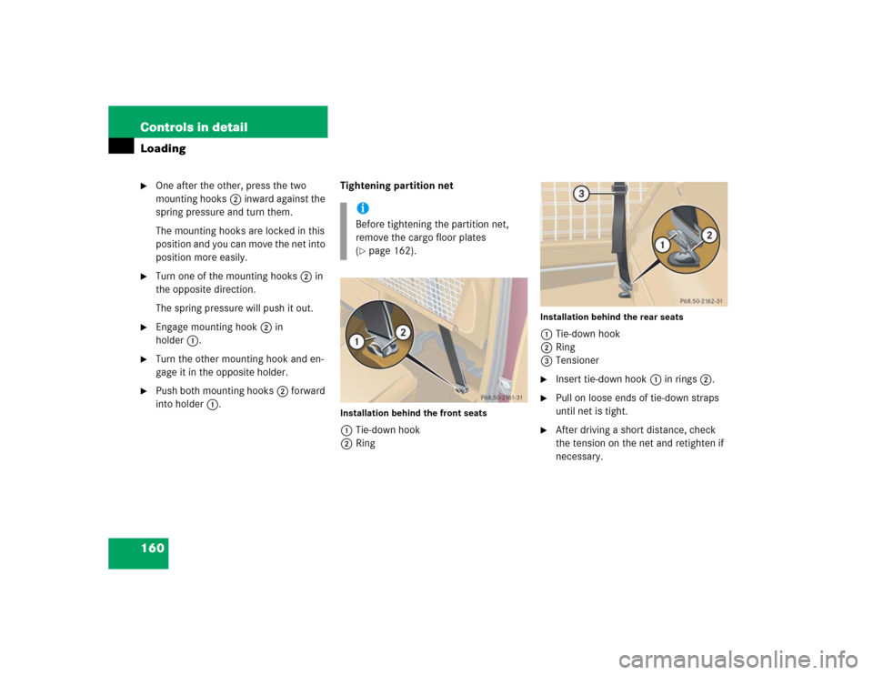
into holder1.Tightening partition net
Installation behind the front seats1Tie-down hook
2Ring
Installation behind the rear seats1Tie-down hook
2Ring
3Tensioner�
Insert tie-down hook1 in rings2.
�
Pull on loose ends of tie-down straps
until net is tight.
�
After driving a short distance, check
the tension on the net and retighten if
necessary.
iBefore tightening the partition net,
remove the cargo floor plates
(�page 162).
Page 164 of 344

164 Controls in detailUseful features
�Useful featuresInterior storage spaces Glove box
1Glove box lid release
2Glove box lid
Opening the glove box
�
Grab in recess and pull lid release1.
The glove box lid2 opens downward.
Closing the glove box
�
Push glove box lid up to close.Storage compartment under front
passenger seat*
The storage compartment is lockable with
its separate key.
1Lock cylinder
2Handle
Locking and unlocking the storage com-
partment
�
Turn the key clockwise.
The storage compartment is locked.
�
Turn the key counterclockwise.
The storage compartment is unlocked.
Warning!
G
To help avoid personal injury during a colli-
sion or sudden maneuver, exercise care
when stowing objects in the vehicle. Put lug-
gage or cargo in the cargo compartment if
possible. Do not pile luggage or cargo higher
than the seat backs.
Always use partition net when transporting
cargo. Partition net cannot secure hard or
heavy objects.
Parcel nets cannot secure hard or heavy ob-
jects.
Keep compartment lids closed. This will help
to prevent stored objects from being thrown
about and injuring vehicle occupants during
an accident.
iThe opened glove box is illuminated
with the key in steering lock position1
(�page 33).
Page 165 of 344
165 Controls in detail
Useful features
Opening the storage compartment �
Press the lock cylinder in and pull stor-
age compartment out using handle2.
Closing the storage compartment
�
Push the storage compartment in until
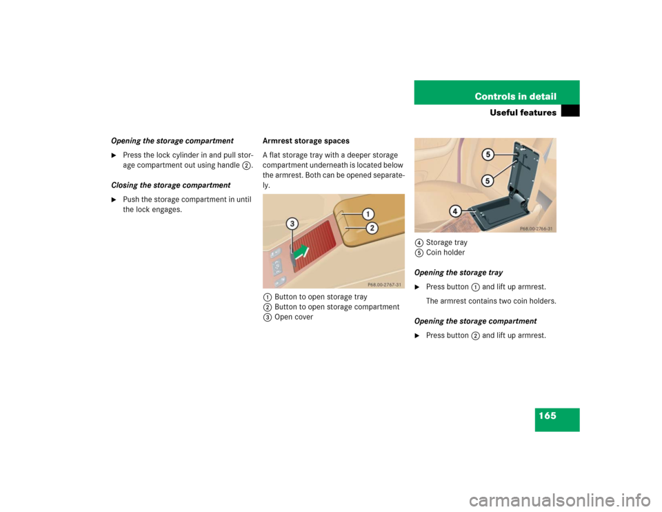
the lock engages.Armrest storage spaces
A flat storage tray with a deeper storage
compartment underneath is located below
the armrest. Both can be opened separate-
ly.
1Button to open storage tray
2Button to open storage compartment
3Open cover4Storage tray
5Coin holder
Opening the storage tray
�
Press button1 and lift up armrest.
The armrest contains two coin holders.
Opening the storage compartment
�
Press button2 and lift up armrest.
Page 168 of 344

168 Controls in detailUseful featuresAshtrays and cigarette lighter Ashtray and cigarette lighter in the
front center console
1Ashtray
2Cigarette lighter
3Cover plate
Opening the ashtray
�
Briefly touch cover plate3.
The ashtray opens automatically.Removing ashtray insert
�
Secure vehicle from movement by set-
ting the parking brake. Move the gear
selector lever to positionN.
Now you have more room to take out
the insert.
�
Grip the insert on the sides and pull it
out upwards.
Reinstalling ashtray insert
�
Install ashtray insert.
�
Close the ashtray.
Warning!
G
Never touch the heating element or sides of
the cigarette lighter; they are extremely hot.
Hold the knob only.
When leaving the vehicle always remove the
key from the steering lock. Do not leave chil-
dren unattended in the vehicle, or with ac-
cess to an unlocked vehicle. Unsupervised
use of vehicle equipment may cause an ac-
cident and / or serious personal injury.iThe cigarette lighter socket can be
used to accommodate electrical acces-
sories up to a maximum of 50 W.
If the engine is off, the battery may be-
come discharged when used for long
periods of time.
Warning!
G
Remove ashtray only with vehicle standing
still. Set the parking brake to secure vehicle
from movement. Move gear selector lever to
positionN. With gear selector lever in
positionN, turn off the engine.
Page 171 of 344

171 Controls in detail
Useful features
You can take and place telephone calls
using the MCS unit.
See separate instruction manual for infor-
mation on how to operate the telephone.
Tele Aid*
Warning!
G
Please do not forget that your primary re-
sponsibility is to drive the vehicle. A driver’s
attention to the road must always be
his / her primary focus when driving. For
your safety and the safety of others, we rec-
ommend that you pull over to a safe location
and stop before placing or taking a tele-
phone call.
If you choose to use the telephone
1 while
driving, please use the hands-free device
and only use the telephone when road,
weather and traffic conditions permit. Some
jurisdictions prohibit the driver from using a
cellular telephone while driving a vehicle.
Only operate the MCS (Modular Control Sys-
tem)
1 if road, weather and traffic conditions
permit.
Bear in mind that at a speed of just 30 mph
(approximately 50 km / h), your vehicle is
covering a distance of approx. 44 feet (ap-
proximately 13.5 m) every second.
1Observe all legal requirements
Warning!
G
Some jurisdictions prohibit the driver from
using a cellular telephone while driving a ve-
hicle. Whether or not prohibited by law, for
safety reasons, the driver should not use the
cellular telephone while the vehicle is in mo-
tion.
Stop the vehicle in a safe location before an-
swering or placing a call.
!The initial activation of the Tele Aid sys-
tem may only be performed by com-
pleting the subscriber agreement and
placing an acquaintance call using the
SOS button. Failure to complete either
of these steps will result in a system
that is not activated. If the system is
not activated, the indicator lamp in the
SOS button stays on after turning key
in steering lock to position2
(�page 33) and the message
TELE
AID – NOT ACTIVATED
will be shown in
the MCS display for approximately
10 seconds.
If you have any questions regarding ac-
tivation, please call the Response Cen-
ter at 1-800-756-9018 (in the USA) or
1-888-923-8367 (in Canada).
Page 172 of 344

The Tele Aid system consists of three
types of response:�
automatic and manual emergency
�
roadsid")
172 Controls in detailUseful featuresThe Tele Aid system
(Telematic Alarm Identification on
Demand)
The Tele Aid system consists of three
types of response:�
automatic and manual emergency
�
roadside assistance and
�
information.
The Tele Aid system is operational provid-
ing that the vehicle’s battery is charged,
properly connected, not damaged and cel-
lular and GPS coverage is available.
The speaker volume of a Tele Aid call can
be adjusted using the volume control on
the MCS unit.
�
To activate, press the SOS button, the
Roadside Assistance button• or
the Information button¡, depend-
ing on the type of response required.Shortly after the completion of your ac-
quaintance call, you will receive a user ID
and password via first call mail. By visiting
www.mbusa.com and selecting “Tele Aid”
(USA only), you will have access to account
information, remote door unlock, profile
and more.System self-check
Initially, after turning the key in the steer-
ing lock to position2, malfunctions are de-
tected and indicated (the indicator lamps
in the SOS button, the Roadside Assis-
tance button• and the Information
button¡ stay on longer than
10 seconds or do not come on). The mes-
sage
TELE AID - VISIT WORKSHOP
ap-
pears for approx. 10 seconds in the MCS
display.
iThe SOS button, the Roadside Assis-
tance button• and the Information
button¡ are located in the over-
head control panel.!The Tele Aid system utilizes the cellular
network for communication and the
GPS (G
lobal P
ositioning S
ystem) satel-
lites for vehicle location. If either of
these signals are unavailable, the Tele
Aid system may not function and if this
occurs, assistance must be summoned
by other means.
Page 176 of 344

176 Controls in detailUseful featuresWhen the connection is established, the
message
ROADSIDE ASSISTANCE –
CALL CONNECTED
appears in the MCS dis-
play. The Tele Aid system will transmit data
generating the vehicle identification num-
ber, model, color and location (subject to
availability of cellular and GPS signals).
A voice connection between the Roadside
Assistance dispatcher and the occupants
of the vehicle will be established. When a
voice connection is established the audio
system mutes and the message
TELE AID
– ROADSIDE ASSISTANCE CALL ACTIVE
ap-
pears in the MCS display.
�
Describe the nature of the need for as-
sistance.The Mercedes-Benz Roadside assistance
dispatcher will either dispatch a qualified
Mercedes-Benz technician or arrange to
tow your vehicle to the nearest
Mercedes-Benz Light Truck Center. For
services such as labor and / or towing,
charges may apply. Refer to the Roadside
Assistance manual for more information.
These programs are only available in the
USA:
�
Sign and Drive services: Services such
as jump start, a few gallons of fuel or
the replacement of a flat tire with the
vehicle spare tire are obtainable,
�
Remote Vehicle Diagnostics: This func-
tion permits the Mercedes-Benz Road-
side Assistance dispatcher to
download malfunction codes and actu-
al vehicle data.
iWhile the call is connected you can
change to navigation menu by pressing
NAVI button on the MCS unit.
iThe indicator lamp in the Roadside As-
sistance button• remains illumi-
nated in red for approx. ten seconds
during the system self-check after turn-
ing the key in the steering lock to
position2 (together with the SOS but-
ton and the Information button¡).
See system self-check (
�page 172)
when the indicator lamp does not light
up in red or stays on longer than ap-
proximately ten seconds.