Page 191 of 4264
REAR AXLE 4B-27
Note :
�
�� � Do not overtighten or loosen and then
retighten the nut.
�
�� � Pinion nut torque will be in the range of 245-
294 N�
�� �m (25-30 kg�
�� �m/181-217 lb�
�� �ft).
425RW018
d. Using punch 5-8840-2293-0, stake the flange
nut at two points.
Note :
When staking, be sure to turn the nut to ensure
that there is no change in bearing preload. Make
sure NOTE: of preload again as instructed in c.
RTW34BSH000201
11. Adjust ring gear backlash.
a.
Attach the side bearing to the differential
assembly without shims by using installer 5-
8840-2162-0 and grip 5-8840-0007-0.
425L100010
b. Insert the differential cage assembly with
bearing outer races into the side bearing bores
of the carrier.
Page 254 of 4264
4C1-34 FRONT WHEEL DRIVE
Important Operations
2. Outer Bearing Outer Race
Installer : 9-8522-1141-0
(J-24256)
Grip : 5-8840-0007-0
(J-8092)
3. Inner Bearing Outer Race
Installer : 9-8522-1274-0
Grip : 5-8840-0007-0
(J-8092)
4. Adjust Shim
Adjustment of drive pinion mounting distance
(1) Apply gear oil to the inner and outer drive pinion bearing.
Clean the pinion setting gage set.
Then install the gage set together with the inner and oute
r
bearings.
1. Pilot : 5-8840-2085-0
(J-21777-42)
2. Nut and bolt : 5-8840-2089-0
(J-23597-9)
3. Gage plate : 5-8840-2087-0
(J-23597-7)
Page 295 of 4264
FRONT WHEEL DRIVE 4C1-75
SPECIAL SERVICE TOOL
ITEM NO. ILLUSTRATION PART NO. PART NAME
FAL-1
5-8840-0013-0
(J-22888)
Side bearing puller
FAL-14
9-8521-1743-0
(J-8107-2)
Side bearing plug adapter
FAL-3
5-8840-0133-0
(J-8614-01)
Pinion flange holder
FAL-8
9-8521-5032-0
Final pinion spindle
FAL-10
5-8840-0015-0
(J-22912-01)
Separator
FAL12
9-8522-1141-0
(J-24256)
Outer bearing outer race
installer
OTL-1
5-8840-0007-0
(J-8092)
Driver handle
FAL-16
9-8522-1274-0
(J-24252)
Inner bearing outer race
installer
FAL-34
5-8840-2085-0
(J-21777-42)
Pilot
Page 875 of 4264
ELECTRICAL-BODY AND CHASSIS 8A-217
PARTS LOCATION 4JH1-TC
RTW38DXF007601
Page 935 of 4264
ELECTRICAL-BODY AND CHASSIS 8A-277
140R300007
Thermo Unit Inspection
INSPECTION
Use a circuit tester to measure the thermo unit resistance.
Replace the unit when the result of inspection is found
abnormal.
Temperature
Check
condition 60�C
(140�F) 115�C
(239�F)
Resistance
value (�)
168 �3.5 +2.5
30.9 –2.0
041R300002
Fuel Tank Unit Inspection
Measure the fuel tank unit resistance between the connector
terminals 1
F-2 and 3 F-2 while shifting the float from “E”
to “F” point.
Fuel Tank Resistance
Level Float position
mm Standard resistance
�
F (B) 217.5 +2.2
17 –0.8
1/2 (A) 105.1 (C24SE,
4JA1-L, 6VE1)
112.8 (4JA1-TC,
4JH1-TC)
45 � 4.5
E (C) 16.2 120 � 2.0
Page 1019 of 4264
ELECTRICAL-BODY AND CHASSIS 8A-361
TRANSFER CASE CONTROL MODULE
PARTS LOCATION (RHD)
RTW48AXF021701 & RTW48AXF021801
Page 1376 of 4264

6E–4 4JA1/4JH1 ENGINE DRIVEABILITY AND EMISSIONS
MALFUNCTION ....................................... 6E-196
DIAGNOSTIC TROUBLE CODE (DTC) P0251
(SYMPTOM CODE 7) (FLASH CODE 53)
INJECTION PUMP MALFUNCTION ....... 6E-196
DIAGNOSTIC TROUBLE CODE (DTC) P0251
(SYMPTOM CODE 9) (FLASH CODE 53)
INJECTION PUMP MALFUNCTION ....... 6E-196
DIAGNOSTIC TROUBLE CODE (DTC) P0251
(SYMPTOM CODE A) (FLASH CODE 53)
INJECTION PUMP MALFUNCTION ....... 6E-196
DIAGNOSTIC TROUBLE CODE (DTC) P0251
(SYMPTOM CODE B) (FLASH CODE 53)
INJECTION PUMP MALFUNCTION ....... 6E-196
DIAGNOSTIC TROUBLE CODE (DTC) P0251
(SYMPTOM CODE D) (FLASH CODE 53)
INJECTION PUMP MALFUNCTION ....... 6E-196
DIAGNOSTIC TROUBLE CODE (DTC) P0251
(SYMPTOM CODE E) (FLASH CODE 53)
INJECTION PUMP MALFUNCTION ....... 6E-196
Circuit Description ..................................... 6E-197
Diagnostic Aids .......................................... 6E-197
Diagnostic Trouble Code (DTC) P0251
(Symptom Code 6) (Flash Code 53)
Injection Pump Malfunction ..................... 6E-197
Diagnostic Trouble Code (DTC) P0251
(Symptom Code 7) (Flash Code 53)
Injection Pump Malfunction ..................... 6E-199
Diagnostic Trouble Code (DTC) P0251
(Symptom Code 9) (Flash Code 53)
Injection Pump Malfunction ..................... 6E-203
Diagnostic Trouble Code (DTC) P0251
(Symptom Code A) (Flash Code 53)
Injection Pump Malfunction ..................... 6E-204
Diagnostic Trouble Code (DTC) P0251
(Symptom Code B) (Flash Code 53)
Injection Pump Malfunction ..................... 6E-205
Diagnostic Trouble Code (DTC) P0251
(Symptom Code D) (Flash Code 53)
Injection Pump Malfunction ..................... 6E-206
Diagnostic Trouble Code (DTC) P0251
(Symptom Code E) (Flash Code 53)
Injection Pump Malfunction ..................... 6E-207
DIAGNOSTIC TROUBLE CODE (DTC) P0335
(SYMPTOM CODE B) (FLASH CODE 43)
CRANKSHAFT POSITION SENSOR
CIRCUIT MALFUNCTION ....................... 6E-208
DIAGNOSTIC TROUBLE CODE (DTC) P0335
(SYMPTOM CODE D) (FLASH CODE 43)
CRANKSHAFT POSITION SENSOR
MALFUNCTION ....................................... 6E-208
DIAGNOSTIC TROUBLE CODE (DTC) P0335
(SYMPTOM CODE E) (FLASH CODE 43)
ENGINE SPEED INPUT CIRCUITRANGE/PERFORMANCE ....................... 6E-208
Circuit Description ...................................... 6E-209
Diagnostic Aids .......................................... 6E-209
Diagnostic Trouble Code (DTC) P0335
(Symptom Code B) (Flash Code 43)
Crankshaft Position Sensor Circuit
Malfunction .............................................. 6E-209
Diagnostic Trouble Code (DTC) P0335
(Symptom Code D) (Flash Code 43)
Crankshaft Position Sensor Malfunction .. 6E-209
Diagnostic Trouble Code (DTC) P0335
(Symptom Code E) (Flash Code 43) Engine
Speed Input Circuit Range/Performance . 6E-214
DIAGNOSTIC TROUBLE CODE (DTC) P0380
(SYMPTOM CODE 4) (FLASH CODE 66)
GLOW RELAY CIRCUIT VOLTAGE LOW 6E-217
DIAGNOSTIC TROUBLE CODE (DTC) P0380
(SYMPTOM CODE 8) (FLASH CODE 66)
GLOW RELAY CIRCUIT VOLTAGE HIGH 6E-217
Circuit Description ...................................... 6E-217
Diagnostic Aids .......................................... 6E-217
Diagnostic Trouble Code (DTC) P0380
(Symptom Code 4) (Flash Code 66)
Glow Relay Circuit Voltage Low .............. 6E-218
Diagnostic Trouble Code (DTC) P0380
(Symptom Code 8) (Flash Code 66) Glow
Relay Circuit Voltage High ....................... 6E-221
DIAGNOSTIC TROUBLE CODE (DTC) P0381
(SUB CODE 4) (FLASH CODE 67) GLOW PLUG
INDICATOR CIRCUIT VOLTAGE LOW .. 6E-222
DIAGNOSTIC TROUBLE CODE (DTC) P0381
(SUB CODE 8) (FLASH CODE 67) GLOW PLUG
INDICATOR CIRCUIT VOLTAGE HIGH . 6E-222
Circuit Description ...................................... 6E-222
Diagnostic Aids .......................................... 6E-222
Diagnostic Trouble Code (DTC) P0381
(Symptom Code 4) (Flash Code 67) Glow
Plug Indicator Circuit Voltage Low ........... 6E-222
Diagnostic Trouble Code (DTC) P0381
(Symptom Code 8) (Flash Code 67) Glow
Plug Indicator Circuit Voltage High .......... 6E-226
DIAGNOSTIC TROUBLE CODE (DTC) P0400
(SYMPTOM CODE 3) (FLASH CODE 32)
EXHAUST GAS RECIRCULATION FLOW
EXCESSIVE DETECTED ........................ 6E-227
DIAGNOSTIC TROUBLE CODE (DTC) P0400
(SYMPTOM CODE 4) (FLASH CODE 32)
EXHAUST GAS RECIRCULATION CIRCUIT
SHORT TO GROUND OR OPEN CIRCUIT 6E-227
DIAGNOSTIC TROUBLE CODE (DTC) P0400
(SYMPTOM CODE 5) (FLASH CODE 32)
EXHAUST GAS RECIRCULATION FLOW
INSUFFICIENT DETECTED .................... 6E-227
Page 1589 of 4264

4JA1/4JH1 ENGINE DRIVEABILITY AND EMISSIONS 6E–217
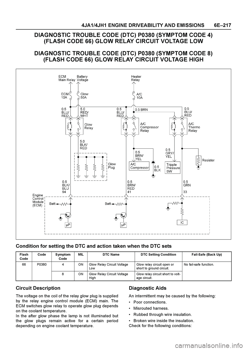
DIAGNOSTIC TROUBLE CODE (DTC) P0380 (SYMPTOM CODE 4)
(FLASH CODE 66) GLOW RELAY CIRCUIT VOLTAGE LOW
DIAGNOSTIC TROUBLE CODE (DTC) P0380 (SYMPTOM CODE 8)
(FLASH CODE 66) GLOW RELAY CIRCUIT VOLTAGE HIGH
Condition for setting the DTC and action taken when the DTC sets
Circuit Description
The voltage on the coil of the relay glow plug is supplied
by the relay engine control module (ECM) main. The
ECM switches glow relay to operate glow plug depends
on the coolant temperature.
In the after glow phase the lamp is not illuminated but
the glow plugs remain active for a certain period
depending on engine coolant temperature.
Diagnostic Aids
An intermittent may be caused by the following:
Poor connections.
Misrouted harness.
Rubbed through wire insulation.
Broken wire inside the insulation.
Check for the following conditions:
Flash
CodeCode Symptom
CodeMIL DTC Name DTC Setting Condition Fail-Safe (Back Up)
66 P0380 4 ON Glo w Re la y Circuit Volta ge
Lo wGlow relay circuit open or
sho rt to ground circuit.No fa il-sa fe fun ctio n.
8 ON Glo w Re la y Circuit Volta ge
HighGlo w re la y circuit short to vo lt-
age circuit.