Page 3962 of 4264

7A1-16 CONSTRUCTION AND FUNCTION
Control Valve Fail-safe Function
� To prevent interlocking due to engagement of more than three clutches and brakes at the same time, the
2-4 brake fail-safe valve A and B, and the low & reverse brake fail-safe valve A and B are provided.
� When oil pressure is generated in the high clutch and the low clutch, the 2-4 brake solenoid is turned ON
to drain the oil pressure applied to the 2-4 brake.
� When oil pressure is generated in the high clutch or 2-4 brake, the low & reverse brake solenoid is turned
ON to drain the oil pressure applied to the low & reverse brake.
Oil Pressure Switch
� The oil pressure switch detects the oil pressure supply condition to the clutch and brake and sends the
detection result to the TCM.
� The oil pressure switch is turned ON when the oil pressure reaches the switch working pressure and
turned OFF when the pressure decreases below the specified value.
� The high clutch oil pressure switch detects the high clutch oil pressure, 2-4 brake oil pressure switch the
2-4 brake oil pressure, and the low & reverse brake oil pressure switch the low & reverse brake oil
pressure respectively.
Figure 27. Oil Pressure Switch Figure 28. Location of Oil Pressure Switch
Page 3963 of 4264

CONSTRUCTION AND FUNCTION 7A1-17
ATF Thermo Sensor
� The ATF thermo sensor detects the ATF temperature in the oil pan and sends signal to the TCM.
� The ATF thermo sensor is of the thermister type that the resistance value changes according to the ATF
oil temperature.
� The lower is the ATF temperature, the larger is the resistance, and vice versa.
� When the ATF temperature exceeds 145�C, the TCM lights up the ATF temperature warning lamp in the
meter. When the ATF temperature decreases below 128�C, the ATF temperature warning lamp goes out.
� The ATF thermo sensor is installed to the lower control valve body and integrated with the harness
assembly.
10.0 100.0 1,000.0 10,000.0 100,000.0
-30 -20 -10 0 10 20 30 40 50 60 70 80 90 100 110 120 130 140 150 160
A TF Temperature (°C)
Resistance (�
)
Figure 29. Characteristic of Thermo Sensor
Figure 30. Location of Thermo Sensor
ATF Temperature
(deg. C) Resistance (Ohm)
(Approximately) ATF Temperature
(deg. C) Resistance (Ohm)
(Approximately)
-30 29,614 100 190
-20 16,705 110 149
-10 9,842 120 118
0 6,028 128 98
20 2,500 130 94
40 1,160 135 84
50 819 140 76
60 591 145 68
80 324 150 62
Page 3964 of 4264
7A1-18 CONSTRUCTION AND FUNCTION
Terminal Assembly
Pin No. Connected to Connected TCMPin No.
6 Line Pressure Solenoid B23
12 Low & Reverse Brake Oil Pressure Switch B12
5 Low & Reverse Brake Duty Solenoid B6
11 Ground Return B22
4 Lock-up Duty Solenoid B17
10 High Clutch Duty Solenoid B8
3 Low Clutch Duty Solenoid B9
9 2-4 Brake Duty Solenoid B7
2 Oil Thermo Sensor B4
8 Oil Thermo Sensor Ground B14
1 High Clutch Oil Pressure Switch B20
7 2-4 Brake Oil Pressure Switch B1
123456
891011127
Terminal Assembly Inhibitor Switch
Figure 31. Pin Assignment Figure 32. Location of Terminal Assembly
Page 3965 of 4264
CONSTRUCTION AND FUNCTION 7A1-19
OIL PASSAGE
Figure 33. Oil Passage of Transmission Case
Page 3966 of 4264
7A1-20 CONSTRUCTION AND FUNCTION
Figure 34. Oil Passage of Oil Pump
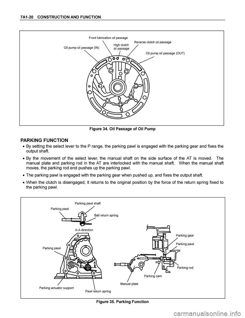
PARKING FUNCTION
� By setting the select lever to the P range, the parking pawl is engaged with the parking gear and fixes the
output shaft.
� By the movement of the select lever, the manual shaft on the side surface of the AT is moved. The
manual plate and parking rod in the AT are interlocked with the manual shaft. When the manual shaft
moves, the parking rod end pushes up the parking pawl.
� The parking pawl is engaged with the parking gear when pushed up, and fixes the output shaft.
� When the clutch is disengaged, it returns to the original position by the force of the return spring fixed to
the parking pawl.
Figure 35. Parking Function
Page 3971 of 4264

� The TCM is fitted side of brake pedal by means of two stud bolts.
� The TCM judges necessary line pressure, gear shifting point")
CONSTRUCTION AND FUNCTION 7A1-25
TRANSMISSION CONTROL MODULE (TCM)
� The TCM is fitted side of brake pedal by means of two stud bolts.
� The TCM judges necessary line pressure, gear shifting point and lock-up operation based on electrical
signals from switches and sensors and sends appropriate signals to solenoids.
�� �� �� �� �� �� �� � �
�� �� �� �� �� �� �� � �
�
� �
� �
� �
� �
� �
� �
�
�
� �
� �
� �
� �
� �
� �
� �
�
�
�
� � � � � �
� � �
� � � � � � �
� � �
�
Connect to White Connector Connect to Grey Connector
Figure 49. Pin Assignment
Pin No. Pin Assignment Pin No.Pin Assignment
B1 2-4 Brake Oil Pressure Switch A1 V BATT (Battery Back-up Power Supply)
B2 2 Range Switch A2 P Range Switch
B3 Turbine Sensor A3 Brake Switch
B4 ATF Thermo Sensor A4 3rd Start Indicator Lamp
B5 Ground A5 K-Line Signal (Tech 2 Serial Communication)
B6 Low & Reverse Brake Duty Solenoid A6 No Connection
B7 2-4 Brake Duty Solenoid A7 Engine Speed Sensor
B8 High Clutch Duty Solenoid A8 No Connection
B9 Low Clutch Duty Solenoid A9 No Connection
B10 N Range Switch A10 Vehicle Speed Sensor Out (2WD Only)
B11 D Range Switch A11 3rd START Select Switch
B12 Low & Reverse Brake Oil Pressure Switch A12 4L Mode Switch (4WD Only)
B13 Vehicle Speed Sensor A13 No Connection
B14 ATF Thermo Sensor Ground A14 No Connection
B15 Ground A15 No Connection
B16 No Connection A16 Throttle Position Sensor
B17 Lock-up Duty Solenoid A17 3 Range Switch
B18 Vign �Ignition Power Supply) A18 DIAG Switch (Test Switch)
B19 R Range Switch A19 A/T OIL TEMP Indicator Lamp
B20 High Clutch Oil Pressure Switch A20 CHECK TRANS Indicator Lamp
B21 L Range Switch A21 POWER DRIVE Indicator Lamp
B22 Ground (Shift Solenoid) A22 No Connection
B23 Line Pressure Solenoid A23 No Connection
B24 Vign (Ignition Power Supply) A24 POWER DRIVE Select Switch
Page 3972 of 4264

7A1-26 CONSTRUCTION AND FUNCTION
CONTROL MECHANISM
CONTENT OF FUNCTION AND CONTROL
Item Description
Line pressure control TCM issues a signal according to the vehicle traveling, engine load and other conditions to
TCM and the ON/OFF type line pressure solenoid is driven to switch the line pressure to
high or low pressure.
The line pressure solenoid is switched to the low pressure side when the solenoid is turned
ON (power supplied) and to the high pressure side when turned OFF (no power supplied).
In the forward travel range (D, 3, 2, L range), the line pressure decreases lower than that in
the P, N, and R range through the oil pressure circuit for the forward travel range.
Gear shift control The TCM issues a shift solenoid drive signal based on the traveling mode switch, inhibitor
switch, vehicle speed, throttle opening and other input signal to control the optimum gear
position automatically.
Speed change features have been set up to the TCM; the normal mode is suited to usual
traveling and the power mode is appropriate when the vehicle is loaded or accelerates the
speed.
In addition, speed change features used only for high oil temperature, hill climbing, and
down have been set up to the TCM, which are automatically switched depending on the
traveling conditions.
When the oil temperature is low (below 10�C), speed change from the third to the fourth
speed is prohibited by the gear shift control.
Shift pattern selection
control
According to a vehicle condition, the TCM selects the following shift pattern.
Selection Priority Shift Pattern 3rd Start Lamp Power Drive Lamp
High High Temperature OFF OFF
3rd Start ON
4L
Power SW Off
OFF
Down Slop Power SW On
Power ON
Up Slope
Low Normal
OFF
OFF
- High temperature mode -
High temperature mode setting condition
ATF temperature: More than 123�C
Above condition is met for more than 10 seconds.
High temperature mode cancel condition
ATF temperature: Less than 116�C
Above condition is met for more than 10 seconds.
- 3rd start mode -
3rd start mode setting condition
3rd start switch: On � Off (Pushed)
Vehicle speed: Less than 11km/h
ATF temperature: Less than 115�C
Throttle position: Less than 8%
Select lever position: D range
Above conditions are met at the same time.
3rd start mode reset condition
3rd start switch: On � Off again(Pushed again)
Vehicle speed: More than 34km/h
Select lever position: Other than D range
At least, one of above conditions is met.
Page 3973 of 4264

CONSTRUCTION AND FUNCTION 7A1-27
Item Description
- 4L mode -
4L mode setting condition
4L switch: On
Vehicle speed: More than 5km/h
Above conditions are met at the same time.
4L mode reset condition
4L switch: Off
Vehicle speed: Less than 4km/h
Above conditions are met at the same time.
- Down slope mode -
Down slope mode setting condition
Brake switch: On
Engine idle condition: More than 2.5 seconds
Select lever position: D or 3 range
Vehicle speed: More than 55km/h
Vehicle speed change: More than 1km/h
Above conditions are met at the same time.
Down slope mode reset condition
Engine idle condition: Not idle condition
Select lever position: Other than D or 3 range
At least, one of above conditions is met.
- Power Mode -
When power drive switch is On at only D range or 3 range, the shift change is performed by
1 – 4 speed based on shift diagram set as power pattern.
- Up slope mode -
Up-slope reasoning value is calculated from the average throttle angle and the average
acceleration. Otherwise, up-slope reasoning value is calculated from the vehicle speed.
TCM judges as up-slope mode when the former is bigger than latter.
Lock-up control The lock-up solenoid adjusts the pressure based on the signal from the TCM according to
the vehicle speed, throttle opening and other input signals based on the pre-set lock-up
point to control the lock-up.
Smooth lock-up control engages and disengages the clutch smoothly at the time of lock-up.
When the oil temperature is low (below 20�C) or high (above 128�C), lock-up is prohibited
even when the vehicle is at a lock-up speed.
The lock-up is disengaged also when the throttle is closed.
Direct electronic shift
control (DESC)
The duty cycle type solenoid is used for each clutch and brake. The solenoid adjusts the
clutch pressure to be suited to the engine load and vehicle traveling condition based on the
signal from the TCM. The pressure switch provided in the control valve oil passage sends
the oil pressure condition to the TCM to control the disengagement and engagement of the
clutch and brake directly and finely.
Learning control Learning is controlled to correct the oil pressure control timing to engage or disengage the
clutch optimally in order to compensate changes of the engine performance and changes
of the transmission with time. It is controlled to bring the speed-change time closer to the
value pre-set to the TCM.