Page 3929 of 4264
UNIT REPAIR (AW30–40LE) 7A4–121
Transmission Case
Disassembled View
24 9RY 0 0001
E nd O FCallo ut
Disassembly
1. Using a chisel, cut off the spacer and remove it from
the shaft.
24 9RY 0 0002
Legend
(1) Spacer
(2) Pin
(3) Manual valve lever shaft(4) Manual valve lever
(5) Oil seal
(6) Oil seal
Page 3930 of 4264
7A4–122 UNIT REPAIR (AW30–40LE)
2. Using a punch, drive out the pin.
24 9RY 0 000 3
3. Pull the manual valve lever shaft out through the
case by the threads.
4. Take out the manual valve lever.
5. Using a screwdriver, remove the oil seals.
24 9RY 0 000 4
Reassembly
1. Coat a new oil seal lip with multi purpose grease.
Using special tool, drive in the oil seal.
Oil seal installer : J–37232–2
RTW3 7A SH00 0701
2. Assemble a new spacer to the manual valve lever.
3. Install the manual valve lever shaft to the
transmission case through the manual valve lever
by the threads.
24 9RY 0 0005
Page 3933 of 4264
UNIT REPAIR (AW30–40LE) 7A4–125
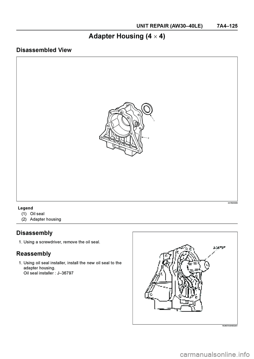
Adapter Housing (4 � 4)
Disassembled View
2 41R20 0005
E nd O FCallo ut
Disassembly
1. Using a screwdriver, remove the oil seal.
Reassembly
1. Using oil seal installer, install the new oil seal to the
adapter housing.
Oi l seal i nstaller : J–36797
RUW3 7A SH00 2401
Legend
(1) Oil seal
(2) Adapter housing
Page 3934 of 4264
7A4–126 UNIT REPAIR (AW30–40LE)
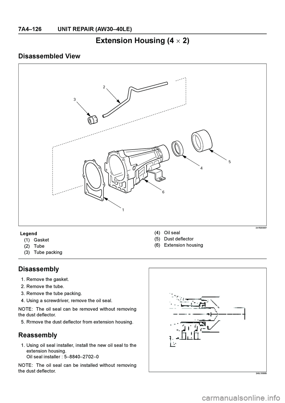
Extension Housing (4 � 2)
Disassembled View
2 41R20 0007
E nd O FCallo ut
Disassembly
1. Remove the gasket.
2. Remove the tube.
3. Remove the tube packing.
4. Using a screwdriver, remove the oil seal.
NOTE: The oil seal can be removed without removing
the dust deflector.
5. Rrmove the dust deflector from ex tension housing.
Reassembly
1. Using oil seal installer, install the new oil seal to the
ex tension housing.
Oi l seal i nstaller : 5–8840–2702–0
NOTE: The oil seal can be installed without removing
the dust deflector.
24 9L10 0005
Legend
(1) Gasket
(2) Tube
(3) Tube packing(4) Oil seal
(5) Dust deflector
(6) Extension housing
Page 3936 of 4264
7A4–128 UNIT REPAIR (AW30–40LE)
Main Data and Specifications
General Specifications
Remaks
Model AW30–40LE
Engine 6VE1 (3.5L)
Type Electronic control planetary gear type
3–element 1–stage 2–phase type
(with lock-up mechanism)
Gear ratio 1st 2.804
2nd 1.532
3rd 1.000
4th (O/D) 0.705
Reverse 2.394
Oil used Name BESCO ATF III
Q'ty (l) 8.7
Torque converter 2100 � 150 Stall speed (rpm)
Friction element
Forward clutch C–15
Number of discs Direct clutch C–24
OD direct clutch C–02
Second coast brake B–1 40 mm Band width or
Number of discs
Second brake B–25
Number of discs First and reverse brake B–36
Overdrive brake B–04
Clutch
One-way clutch No.1 F–122
Number of
sprage One-way clutch No.2 F–228
OD one-way clutch F–024
Planetary gear
Front planetary Sun gear 42
Number of teeth Pinion gear 19
Ring gear 79
Rear planetary Sun gear 33
Pinion gear 23
Ring gear 79
O/D planetary Sun gear 33
Pinion gear 23
Ring gear 79
Page 3940 of 4264
7A4–132 UNIT REPAIR (AW30–40LE)
Special Tools
ILLUSTRATIONTOOL NO.
TOOL NAME
J–37227
Holding fixture
J–3289–20
Holding fixture base
J–37228
Oil pan seal cutter
J–23327–1
Spring compressor
J–9617
Oil seal installer; oil
pump
J–37233
Spring compressor; OD
brake piston
J–29770–A
Oil pressure gauge
J–25048
Spring compressor
J–37236
Reaction sleeve puller;
first and reverse brake
J–37237
Piston puller; first and
reverse brake
J–37232–2
Oil seal installer;
manual valve shaft seal
installer & remover
J–35467
Onennway clutch
testing tool; torque
converter ILLUSTRATIONTOOL NO.
TOOL NAME
Page 3941 of 4264
UNIT REPAIR (AW30–40LE) 7A4–133
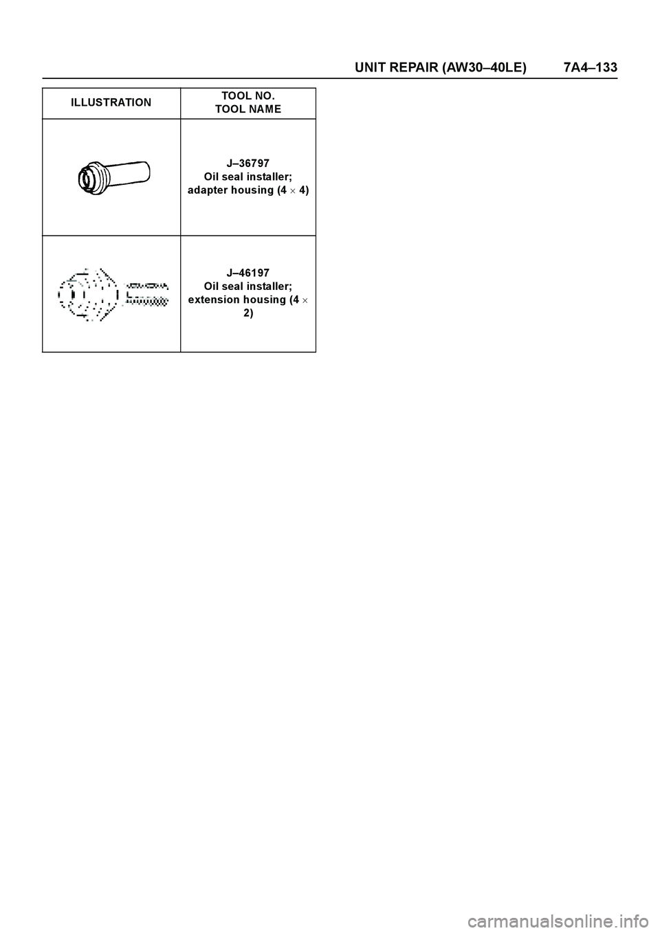
J–36797
Oil seal installer;
adapter housing (4 � 4)
J–46197
Oil seal installer;
extension housing (4 �
2) ILLUSTRATIONTOOL NO.
TOOL NAME
Page 3947 of 4264

CONSTRUCTION AND FUNCTION 7A1-1
SECTION 7A1
CONSTRUCTION AND FUNCTION
TABLE OF CONTENTS
PAGE
DESCRIPTION ..............................................................................................................................7A1- 3
CONSTRUCTION ....................................................................................................................7A1- 3
MAIN DATA AND SPECIFICATION .....................................................................................7A1- 4
NUMBER PLATE LOCATION ...............................................................................................7A1- 5
ELECTRONIC CONTROL COMPONENTS LOCATION ..................................................7A1- 6
TRANSMISSION CONTROL UNIT (TCM) PERIPHERAL CIRCUIT ..............................7A1- 7
STRUCTURE AND FUNCTION OF COMPONENT ...........................................................7A1- 8
TORQUE CONVERTER (WITH LOCK-UP FUNCTION) ..................................................7A1- 8
OIL PUMP .................................................................................................................................7A1- 9
INPUT SHAFT ..........................................................................................................................7A1- 10
OUTPUT SHAFT ......................................................................................................................7A1- 10
GEAR SHIFTING MECHANISM ............................................................................................7A1- 10
CONTROL VALVE ...................................................................................................................7A1- 14
OIL PASSAGE .........................................................................................................................7A1- 19
PARKING FUNCTION .............................................................................................................7A1- 20
INHIBITOR SWITCH ...............................................................................................................7A1- 21
TURBINE SENSOR .................................................................................................................7A1- 22
SPEED SENSOR .....................................................................................................................7A1- 22
THROTTLE POSITION SENSOR (TPS) .............................................................................7A1- 23
ENGINE SPEED SENSOR (=TDC SENSOR) ....................................................................7A1- 23
BRAKE SWITCH ......................................................................................................................7A1- 24
MODE SELECT SWITCH .......................................................................................................7A1- 24
TRANSMISSION CONTROL MODULE (TCM) ..................................................................7A1- 25
CONTROL MECHANISM ............................................................................................................7A1- 26
CONTENT OF FUNCTION AND CONTROL ......................................................................7A1- 26
CONTROL ITEM, INPUT AND OUTPUT .................................................................... 7A1- 29
LINE PRESSURE CONTROL ..................................................................................... 7A1- 30
 7A4–121
Transmission Case
Disassembled View
24 9RY 0 0001
E nd O FCallo ut
Disassembly
1. Using a chisel, cut off the spacer and remove it from
the shaft.
24 9RY 0 0002
Leg")

2. Using a punch, drive out the pin.
24 9RY 0 000 3
3. Pull the manual valve lever shaft out through the
case by the threads.
4. Take out the manual valve lever.
5.")

Main Data and Specifications
General Specifications
Remaks
Model AW30–40LE
Engine 6VE1 (3.5L)
Type Electronic control planetary gear type
3–element 1–stage 2�")

Special Tools
ILLUSTRATIONTOOL NO.
TOOL NAME
J–37227
Holding fixture
J–3289–20
Holding fixture base
J–37228
Oil pan seal cutter
J–23327–1
Spring compres")