Page 4157 of 4264
ON-VEHICLE SERVICE (JR405E) 7A3-5
THROTTLE POSITION SENSOR
1
P1010052
The throttle position sensor (1) is fitted on the throttle
valve body.
Adjust
1. Turn the starter switch to the “ON ” position.
2. Measure the voltage between TPS connecto
r
terminals (B) (output) and (A) (ground).
Note:
� Do not remove the sensor connector.
� Make sure that power source (5.0 � 0.01 V) is
measured between TPS connector terminals (C) and
(A) before measurement at step 2.
Standard voltage :
Throttle Angle TPS
Idling (0%) 0.2 - 0.3 V
WOT (100%) 3.4 – 4.1 V
RTW37ASH0013
3. If the reading is beyond the specified value, loosen
the throttle position sensor fixing bolts, and turn i
t
right or left, so that the specified output voltage be
obtained.
After adjusting, tighten the throttle position sensor
fixing screws (2).
826R300013
Page 4160 of 4264
7A3-8 ON-VEHICLE SERVICE (JR405E)
SPEED SENSOR
The speed sensor is attached to the right side of the
transmission.
240L300001
Legend
1. Inhibitor switch
2. Speed sensor
3. Turbine sensor
Inspect
1. During the driving at speed of 20km/h (12mph) with
“L” range in low gear, measure the voltage between
the TCM connector terminals (B13) and (B5) with a
digital voltmeter.
Standard voltage : approx. 7V (AC range)
RTW47ASH000801
2. If the voltage is out of the standard value, check the
speed sensor pole piece for presence of foreign
meterials and the speeed sensor cable for short o
r
open circuit.
Result of the inspection is normal, replace the speed
sensor.
Torque: 6 N·m (52 lb·in)
Page 4161 of 4264
 7A3-9
TURBINE SENSOR
The turbine sensor is attached to the right side of the
transmission.
Inspect
1. During the driving at speed of 20km/h (12mph) with
“L” ra")
ON-VEHICLE SERVICE (JR405E) 7A3-9
TURBINE SENSOR
The turbine sensor is attached to the right side of the
transmission.
Inspect
1. During the driving at speed of 20km/h (12mph) with
“L” range in low gear, measure the voltage between
the TCM connector terminals (B3) and (B5) with a
digital voltmeter.
Standard voltage : approx. 7V (AC range)
2. If the voltage is out of the standard value, check the
turbine sensor pole piece for presence of foreign
materials and the turbine sensor cable for short o
r
open circuit.
Result of the inspection is normal, replace the
turbine sensor.
Torque: 6 N·m (52 lb·in)
POWER AND 3RD START SWITCH
Inspect
1. Block the wheels.
2. Disconnect the negative battery cable.
3. Pry out the switch from the floor console.
4. Disconnect the harness connector.
5. Check continuity between terminal (5) and (6) at third
(3rd) position.
6. Check continuity between terminals (3) and (6) a
t
power (PWR) position.
7. Replace the power and 3rd start switch when the
result of inspection is found abnormal.
8. Connect the harness connector.
9. Connect the negative battery cable.
10. Remove the wheel blocks.
238R300003
Page 4168 of 4264
7A3-16 ON-VEHICLE SERVICE (JR405E)
SOLENOIDS, OIL PRESSURE SWITCH AND OIL TEMPERATURE
SENSOR
244L300003
Legend
1. High clutch oil pressure switch connector
(wire color: Gray)
2. 2-4 brake oil pressure switch connector
(wire color: Brown)
3. Low and reverse brake oil pressure switch connector
(wire color: White)
4. Low and reverse brake duty solenoid connector
(wire color: Pink and White)
5. High clutch duty solenoid connector
(wire color: Green and Gray)
6. Lock-up duty solenoid connector
(wire color: Yellow and Black)
7. 2-4 brake duty solenoid connector
(wire color: Blue and Brown)
8. Low clutch duty solenoid connector
(wire color: Orange and Black)
9. Line pressure solenoid connector
(wire color: Pink)
Page 4169 of 4264
 7A3-17
Remove or Disconnect
1. Block the wheels.
2. Disconnect the negative battery cable.
3. Drain the fluid.
Refer to “ATF CHANGE” in this section.
4. Rem")
ON-VEHICLE SERVICE (JR405E) 7A3-17
Remove or Disconnect
1. Block the wheels.
2. Disconnect the negative battery cable.
3. Drain the fluid.
Refer to “ATF CHANGE” in this section.
4. Remove the 19 bolts and oil pan.
5. Inspect the bottom of the oil pan and strainer netting
for foreign material (clutch facing and metal
shavings).
If there is an excessive accumulation of foreign
material, the oil strainer must be replaced.
Further inspection is required to determine the
source of the foreign material.
6. Remove the harness assembly (including oil
temperature sensor).
7. Remove the 11 bolts and the solenoid fixing plate.
8. Remove the 6 solenoids and 3 oil pressure switchs.
Inspect
Oil pressure switch
Apply compressed air (392 kPa/4.0 kg/cm2) to the oil
pressure switch to check the oil pressure switch
continuity between the connector and screw.
Oil temperature sensor (harness assembly)
Check the oil temperature sensor resistance between
harness terminals 7 and 6 (ground).
Oil temperature sensor resistance:
2,400~2,600 ohms (20�
�� �C)
244L300011
Solenoid
Measure the resistance of each solenoid.
Resistance:
Brown connector – 3.0~3.4 ohms (20�
�� �C)
Gray connector – 12.0~13.2 ohms (20�
�� �C)
White connector – 12.2~13.4 ohms (20�
�� �C)
Install or connect
1. Install the O-rings to each of the solenoids.
2. Install the 6 solenoids and 3 oil pressure switchs.
Line pressure solenoid bolt torque:
8 N·m (69 lb·in)
Oil pressure switch bolt torque:
4.4 N·m (39 lb·in)
3. Install the solenoid fixing plate together with the
harness brackets.
Number Length (Color)
Solenoid fixing plate bolt
(A)
(B)
4
7
16 mm (0.63 in) (Gold)
45 mm (1.77 in) (Silver)
Bolt torque : 8 N·m (69 lb·in)
4. Install the harness assembly.
5. If removed, install the oil strainer.
Number Length (Color)
Oil strainer bolt
(C)
(D)
9
4
13 mm (0.51 in) (Silver)
45 mm (1.77 in) (Silver)
Bolt torque : 8 N·m (69 lb·in)
6. Install the new gasket and oil pan.
Bolt torque : 8 N·m (69 lb·in)
7. Fill the fluid.
Refer to “ATF CHANGE” in this section.
8. Connect the negative battery cable.
9. Remove the wheel blocks.
Page 4171 of 4264
 7A3-19
Install or Connect
1. Align the manual valve and the manual plate of the
transmission case.
43ASSY119
2. Install the control valve assembly and tighten the 12")
ON-VEHICLE SERVICE (JR405E) 7A3-19
Install or Connect
1. Align the manual valve and the manual plate of the
transmission case.
43ASSY119
2. Install the control valve assembly and tighten the 12
fixing bolts to the specified torque.
Number of bolts Length Color
10 (A) 40 mm (1.57 in) Gold
2 (B) 30 mm (1.18 in) Gold
Bolt torque : 8 N·m (69 lb·in)
3. Connect the 2 harness connectors.
4. If removed, install the oil strainer.
Refer to “Solenoids, Oil Pressure Switch and Oil
Temperature Sensor” previously in this section.
5. Install the new gasket and oil pan.
Bolt torque : 8 N·m (69 lb·in)
6. Fill the fluid.
Refer to “ATF CHANGE” in this section.
7. Connect the negative battery cable.
8. Remove the wheel blocks.
FLUSHING THE TRANSMISSION FLUID COOLER AND LINE
The fluid cooler and lines may be flushed under the
following condition. This will help prevent more trouble
after the transmission is repaired.
1. When the abnormal amount of debris are found.
2. When the abnormal wear or chips on gears and
shafts are found while overhauling.
3. When the abnormal clutch facing wear and oil
contamination are found.
Procedures
1. Block the wheels.
2. Disconnect negative battery cable.
3. Raise vehicle and support with suitable safety
stands.
4. Disconnect fluid cooler lines at transmission case
and fluid cooler.
5. Flush and back-flush the fluid cooler and lines using
solvent and compressed air.
Note:
DO NOT exceed 197 kPa (29 psi) air pressure or
damage may result to oil cooler.
6. Remove all remaining solvent from the system with
compressed air.
7. Flush the cooling system again with Automatic
Transmission Fluid (ATF).
After the final flush, connect all lines.
Cooler line joint connector torque :
44 N·m (33 lb·ft)
8. Replenish ATF
9. Start engine to test the system for the free flow o
f
fluid. If the flow is restricted, the cooler assembly o
r
lines must be replaced.
Repeated cleaning and flushing may not remove all
debris from the fluid cooler circuit.
Move the select lever through the various ranges and
return to neutral.
Check for fluid level.
If the fluid level is below the specified range, ATF
must be added.
10. Connect negative battery cable.
11. Remove safety stands.
12. Remove wheel blocks.
Page 4177 of 4264
UNIT REPAIR (JR405E) 7A4-3
Disassembly steps
1. Torque converter
� Pull the torque converter free.
NOTE:
Place a pan beneath the torque converter to catch
automatic transmission fluid (ATF) spillage.
� Draining the ATF from the torque converter.
01ASSY101
2. Turbine sensor and speed sensor
� Remove the turbine sensor from the transmission case.
02ASSY103
�
Remove the speed sensor from the transmission case.
03ASSY106
3. Inhibitor switch
Remove the 2 bolts and the inhibitor switch from the
transmission case.
240L300002
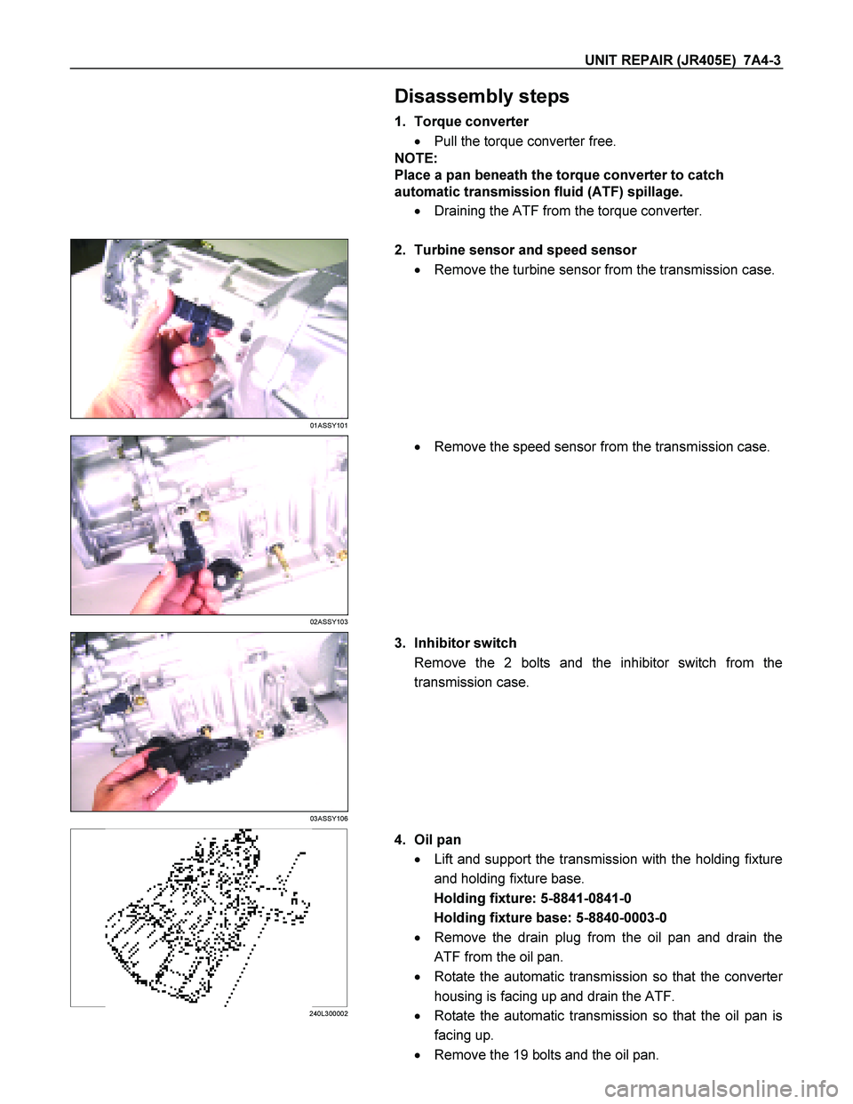
4. Oil pan
� Lift and support the transmission with the holding fixture
and holding fixture base.
Holding fixture: 5-8841-0841-0
Holding fixture base: 5-8840-0003-0
� Remove the drain plug from the oil pan and drain the
ATF from the oil pan.
� Rotate the automatic transmission so that the converte
r
housing is facing up and drain the ATF.
� Rotate the automatic transmission so that the oil pan is
facing up.
� Remove the 19 bolts and the oil pan.
Page 4201 of 4264
 7A4-27
Spring specifications
No. Valve nomenclature Free length
(mm / in) Outside
diameter (mm
/ in) Linear
diameter (mm
/ in) Number of
coils
14 Pressure relief 49.")
UNIT REPAIR (JR405E) 7A4-27
Spring specifications
No. Valve nomenclature Free length
(mm / in) Outside
diameter (mm
/ in) Linear
diameter (mm
/ in) Number of
coils
14 Pressure relief 49.0 / 1.929 7.6 / 0.299 1.1 / 0.043 17.3
15 Pressure regulator 30.5 / 1.201 14.0 / 0.551 1.4 / 0.055 5.7
16 Low and reverse brake fail (A) 22.0 / 0.866 7.0 / 0.276 0.6 / 0.024 10.0
17 Fail 23.0 / 0.906 11.0 / 0.433 0.5 / 0.020 13.2
18 Low and reverse brake amp 19.5 / 0.768 7.9 / 0.311 0.5 / 0.020 6.9
19 2 – 4 brake fail (A) 24.8 / 0.976 8.5 / 0.335 0.9 / 0.035 7.8
20 Low clutch amp (B) 26.0 / 1.024 11.0 / 0.433 0.5 / 0.020 6.9
21
Torque converter relief More than 47.2
/ 1.858 9.2 / 0.362 1.6 / 0.063 20.2
22 2 – 4 brake solenoid accumulator 31.4 / 1.236 9.8 / 0.386 1.3 / 0.051 9.3
23 High clutch accumulator 51.0 / 2.008 6.5 / 0.256 0.8 / 0.031 23.5
Oil pressure switch
Apply compressed air (392 kPa/4.0 kg/cm2) to the oil pressure
switch to check the oil pressure switch continuity between the
connector and screw.
244L300011
Oil temperature sensor (harness assembly)
Check the oil temperature sensor resistance between harness
terminals 7 and 6 (ground).
Oil temperature sensor resistance: 2,400�
�� �2,600 ohms
(20�
�� �)
Solenoid
Measure the resistance of each solenoid.
Resistance:
Brown connector – 3.0�
�� �3.4 ohms (20�
�� �C)
Gray connector – 12.0�
�� �13.2 ohms (20�
�� �C)
White connector – 12.2�
�� �13.4 ohms (20�
�� �C)
Reassembly steps
� Coat the parts with ATF before installing them.
� Install the control valve to the control valve lower body.
� Install the oil filter to the control valve lower body.
 7A3-5
THROTTLE POSITION SENSOR
1
P1010052
The throttle position sensor (1) is fitted on the throttle
valve body.
Adjust
1. Turn the starter switch to t")

SPEED SENSOR
The speed sensor is attached to the right side of the
transmission.
240L300001
Legend
1. Inhibitor switch
2. Speed sensor
3. Turbine sensor")

SOLENOIDS, OIL PRESSURE SWITCH AND OIL TEMPERATURE
SENSOR
244L300003
Legend
1. High clutch oil pressure switch connector
(wire color: Gray)
2. 2-4 brak")