Page 3119 of 4264

TABLE OF CONTENTS
PAGE
Main Data and Specifications .................................................................................")
MSG MODEL 7B-1
SECTION 7B
MANUAL TRANSMISSION
(MSG MODELS)
TABLE OF CONTENTS
PAGE
Main Data and Specifications .................................................................................... 7B - 2
General Description.................................................................................................... 7B - 3
Torque Specification .................................................................................................. 7B - 4
Repair Kit .................................................................................................................... 7B - 6
Removal and Installation ........................................................................................... 7B - 7
Disassembly ............................................................................................................... 7B - 15
Inspection and Repair ............................................................................................... 7B - 25
Reassembly ................................................................................................................ 7B - 29
Special Service Tool .................................................................................................. 7B - 42
Page 3169 of 4264
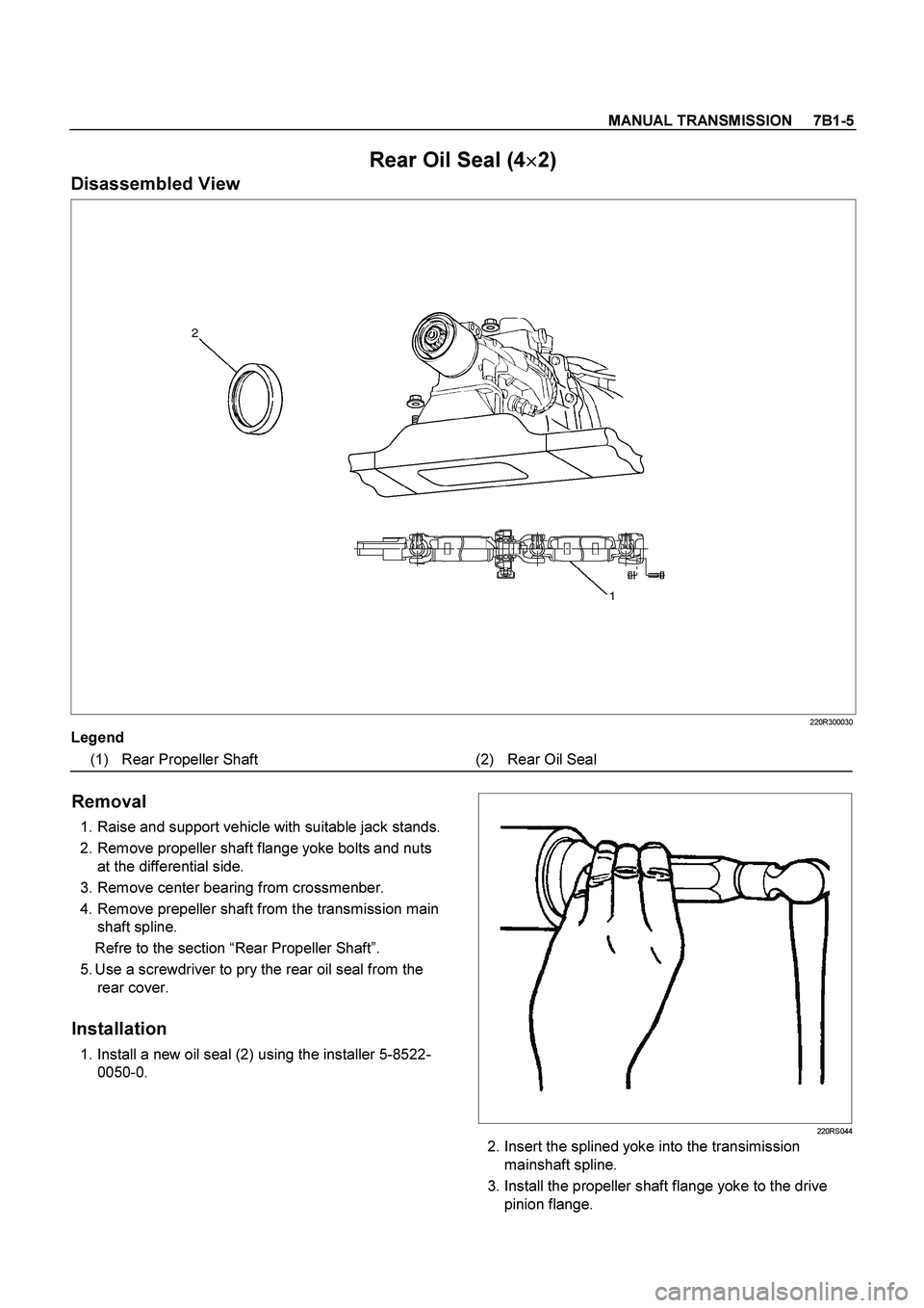
MANUAL TRANSMISSION 7B1-5
Rear Oil Seal (4�
�� �
2)
Disassembled View
220R300030
Legend
(1) Rear Propeller Shaft (2) Rear Oil Seal
Removal
1. Raise and support vehicle with suitable jack stands.
2. Remove propeller shaft flange yoke bolts and nuts
at the differential side.
3. Remove center bearing from crossmenber.
4. Remove prepeller shaft from the transmission main
shaft spline.
Refre to the section “Rear Propeller Shaft”.
5. Use a screwdriver to pry the rear oil seal from the
rear cover.
Installation
1. Install a new oil seal (2) using the installer 5-8522-
0050-0.
220RS044
2. Insert the splined yoke into the transimission
mainshaft spline.
3. Install the propeller shaft flange yoke to the drive
pinion flange.
Page 3318 of 4264
 list with ECM
�
�� � Immobilizer Control Unit (ICU)
DTC
Description Note
B0001
REPLACE ELECTRONIC CONTROL UNIT
(ECU) (IMMOBILIZER FAULT")
11A-32 IMMOBILIZER SYSTEM
Diagnostic Trouble Code (DTC) list with ECM
�
�� � Immobilizer Control Unit (ICU)
DTC
Description Note
B0001
REPLACE ELECTRONIC CONTROL UNIT
(ECU) (IMMOBILIZER FAULT) This error code appears if a RAM /ROM Error was
detected or the EEPROM is defect.
B0002 IMMOBILIZER NOT PROGRAMMED Immobilizer control unit is not programmed.
B0003 TRANSPONDER KEY PROBLEM �
Reading of Transponder information failed with ignition
on transponder has a fault.
�
Hardware fault in reading circuit.
B0004
IMMOBILIZER COIL CIRCUIT (ANTENNA
COIL FAULT) Immobilizer coil has a fault.
B0005 COMMUNICATION LINE W VOLTAGE LOW Short circuit to ground or open circuit.
B0006 COMMUNICATION LINE W VOLTAGE HIGH Short circuit to 12V.
B0007 NO ENGINE REQUEST RECEIVED No ECM Challenge.
B0008 WRONG TRANSPONDER KEY Incorrect security code response received.
B0009 NO TRANSPONDER KEY PROGRAMMED Transponder security code table empty
B0010 UNKNOWN TRANSPONDER KEY Transponder security code not valid.
�
�� � Engine Control Module (ECM: Gasoline Engine {6VE1, C24SE})
DTC Description
Note
P1626 No Response From Immobilizer Refer to Engine Control system section
P1631 Received Response Was Not Correct Refer to Engine Control system section
P1648 Received Incorrect Security Code Refer to Engine Control system section
P1649 Security Code & Security Key Not
Programmed Refer to Engine Control system section
�
�� � Engine Control Module (ECM: Diesel Engine {4JH1-TC, 4JA1-TC})
DTC Description Note
P1610 Seeds and Key File Destroyed Refer to Engine Control system section
P1611 Wrong Security Code Entered Refer to Engine Control system section
P1612/
P1613 Immobilizer No or Wrong Signal Refer to Engine Control system section
P1649 Wrong Transponder Key Refer to Engine Control system section
Page 3321 of 4264
 Yes No
10 Review and record for scan tool Failure Records data
and DTCs.
Was the action complete? �
Go to Step 11 �
11 Following the DTC is stor")
IMMOBILIZER SYSTEM 11A-35
Step Action Value(s) Yes No
10 Review and record for scan tool Failure Records data
and DTCs.
Was the action complete? �
Go to Step 11 �
11 Following the DTC is stored.
Are there DTC B0001 or B0055 stored?
Go to applicable
DTC table after
Go to Step 12 Go to Step 12
12 Clear the DTCs by "Clear the Information "with scan
tool.
Did the DTCs Cleared? �
Go to Step 12 �
13 Select "Display DTCs" with the scan tool.
Are any DTCs stored? �
Go to applicable
DTC table Go to Step 14
14 1. Key position is "ON," engine "OFF."
2. Observe the check engine lamp.
Note: If a key switch is turned ON, check engine lamp
will turn on and a check engine lamp will be turned off
after a few seconds.
Is the check engine lamp "flash"? �
Go to Step 15
Go to Step 20
15 Check the engine control system.
If a problem is found, repair as necessary.
(Refer to section 6E: system check and DTCs)
IMPORTANT:
The replacement ECM must be
programmed the immobilizer data by scan tool.
(Except 4JA1-L Engine)
Was the action complete? �
Go to Step 16 �
16 Check the key.
Is a key peculiar to a vehicle? �
Go to Step 18
Go to Step 17
17 Change into a peculiar key.
IMPORTANT:
If replace the key,
after replace lock
cylinders, perform the following below the items.
� Replace the keys and key cylinders.
� Program the immobilizer system.
(Refer to "Important information on Programming")
Was the action complete? �
Go to Step 18 �
18 Check the immobilizer programming functions.
�
Immobilizer control unit (ICU).
�
Engine control module (ECM).
�
Transponder (Key).
If a problem is found, repair as necessary.
(Refer to "Important information on Programming")
Was the action complete? �
Go to Step 19
�
19 Operate the DTCs by "Clear the Information" with
scan tool.
Was the action complete? �
Go to Step 20 �
20 Attempt to start the engine.
Did the engine start? �
System OK
Refer to
Diagnostic Aids
Page 3383 of 4264
 Yes No
1
2
3
4
5
6
7
8
91. Key position is “ACC”, shut all doors and
bonnet.
2. Observe the antitheft lamp.
Note: When a k")
ANTITHEFT SYSTEM 11B – 37
Antitheft System Check
Step Action Value (s) Yes No
1
2
3
4
5
6
7
8
91. Key position is “ACC”, shut all doors and
bonnet.
2. Observe the antitheft lamp.
Note: When a key switch is “ACC”, antithft
lamp will turn on and a antitheft lamp (LED)
will be flashing after 10 seconds.
Is the antitheft lamp "ON” or flashing?
1. Key position is “ON”, engine “OFF”.
2. Observe the antitheft lamp.
3. Key position is turned “ACC”.
4. Check the antitheft lamp will be turned
flashing and lamp will be turned ACC after 10
seconds.
Is the antitheft lamp flashing?
1. Key position is “OFF”.
2. Install the Tech-2.
3. Key position is “ON” or “OFF”.
4. Attempt to display antitheft data with the
Tech-2.
Does the Tech-2 display antitheft data?
1. Key position is “OFF”, disconnect the
antitheft control unit (ACU).
2. Check the DLC (Data Link Connector) circuit
for an open, short to ground, or short to
voltage.
Also, check the DLC ignition feed circuit for an
open or short to ground and the DLC ground
circuit for an open.
Was a problem found?
Repair or replace the DLC (Data Link Connector)
circuit.
Was the action complete?
1. Check the ACU ground circuit for an open, or
short to voltage. Also, check the ACU ignition
feed circuit for an open or short to ground
and the ACU ground circuit for an open.
2. If a problem is found, repair as necessary.
Was the problem found?
Replace the antitheft control unit (ACU).
IMPORTANT: The replacement ACU must be
programmed the antitheft data by Tech-2.
Was the action complete?
Select “Display DTCs” with the Tech-2.
Are any DTCs stored?
1. Observe the antitheft data list on Tech-2.
2. If a problem is found, repair as necessary.
Was the problem found?—
—
—
—
—
—
—
—
—Go to Step 2
Go to
DTC table
Go to Step 9
Go to Step 5
Go to Step 3
Verfy repair
Go to Step 8
Go to applicable
DTC table
System OKGo to
“No antitheft
lamp”
Go to Step 3
Go to Step 4
Go to Step 6
—
Go to Step 7
—
—
Go to
applicable
section
Page 3417 of 4264
FRONT ALIGNMENT 3A-1
SECTION 3A
FRONT ALIGNMENT
TABLE OF CONTENTS
PAGE
Front End Alignment Inspection and Adjustment .......................................................... 3A- 2
General Description ..................................................................................................... 3A- 2
Inspection .....................................................................................................................3A- 3
Alignment for 4�
�� �2 (Except High Ride Suspension) .......................................................3A- 4
Alignment for 4�
�� �2 (High Ride Suspension) and 4�
�� �4 ......................................................3A- 10
Page 3493 of 4264

FRONT SUSPENSION 3C-1
SECTION 3C
FRONT SUSPENSION
TABLE OF CONTENTS
PAGE
Main Data and Specifications ........................................................................................... 3C- 2
Torque Specifications ....................................................................................................... 3C- 3
Special Parts Fixing Nuts and Bolts ............................................................................ 3C- 3
Front Suspension .............................................................................................................. 3C- 6
General Description ...................................................................................................... 3C- 6
Front Suspension (4�
�� �2 Except High Ride Suspension)............................................. 3C- 8
Front Suspension (4
�
�� �2 High Ride Suspension, 4
�
�� �4) ................................................. 3C- 30
Troubleshooting ............................................................................................................ 3C- 54
Page 3501 of 4264
FRONT SUSPENSION 3C-9
Shock Absorber
Shock Absorber and Associated Parts
RTW440LF001201
Legend
(1)
Shock Absorber ASM with coil
(2)
Nut
(3)
Nut
(4)
Nut
(5)
Lower ball joint Nut and cot ter pin
(6)
Nut
(7)
Bolt
(8)
Cam bolt
Removal
1. Raise the vehicle and support it with suitable
safety stands.
2. Remove wheel and tire assembly. Refer to Wheel
Replacement in this section.
3. Remove nut (6).
CAUTION: Be careful not o break the ball joint boot.


Shock Absorber ASM with coil
(2)
Nut
(3)
Nut
(4)
Nut
(5)
Lower b")