Page 3451 of 4264

RTW33BLF000801
Legend
(1) Pump Assembly
(2) Hose, Suction
(3) Hose, Flexible
(4) Bolt
(5) Connecto")
POWER-ASSISTED STEERING SYSTEM 3B-21
Power Steering Pump and Associated Parts (C24SE)
RTW33BLF000801
Legend
(1) Pump Assembly
(2) Hose, Suction
(3) Hose, Flexible
(4) Bolt
(5) Connector, Pressure switch
Removal
1. Remove the drive belt.
2. Remove the pulley
3. Place a drain pan below the pump.
4. Disconnect the suction hose.
5. Disconnect the flexible hose.
6. Disconnect the oil pressure switch connector.
7. Remove the power steering fixing bolt and remove
the pump assembly.
Installation
1. Install the pump assembly to the pump braket,
tighten the fixing bolt to the specified torque.
Torque: 34-46 N·m (3.5-4.7 kg·m/25-34 lb ft)
2. Connector the oil pressure switch connector.
3. Install the flexible hose.
Tighten the eye bolt to specified torque.
Torque: 49-59 N·m (5.0-6.0 kg·m/36-43 lb ft)
4. Install the pulley and tighten the bolt to the specified
torque.
Torque: 69-88 N·m (7.0-9.0 kg·m/51-65 lb ft)
5. Install the drive belt.
6. Connect the suction hose, then fill and bleed
system.
Refer to Bleeding the Power Steering System in this
section.
Page 3456 of 4264
3B-26 POWER-ASSISTED STEERING SYSTEM
Power Steering Pump and Associated Parts (6VE1)
RTW33BLF000701
Legend
(1) Pump Assembly
(2) Hose, Suction
(3) Hose, Flexible
(4) Bolt
(5) Connector, Pressure switch
Removal
1. Remove the drive belt.
2. Place a drain pan below the pump.
3. Disconnect the suction hose.
4. Disconnect the flexible hose.
5. Disconnect the oil pressure switch connector.
6. Remove the power steering fixing bolt and remove
the pump assembly.
Installation
1. Install the pump assembly to the pump braket,
tighten the fixing bolt to the specified torque.
Torque: 31-63 N·m (3.2-6.4 kg·m/23-46 lb ft)
2. Connector the oil pressure switch connector.
3. Install the flexible hose.
Tighten the eye bolt to specified torque.
Torque: 49 - 59 N·m (5.0 – 6.0 kg·m/36 - 43 lb ft)
4. Install the drive belt.
5. Connect the suction hose, then fill and bleed
system.
Refer to Bleeding the Power Steering System in this
section.
Page 3461 of 4264

POWER-ASSISTED STEERING SYSTEM 3B-31
Supplemental Restraint System Steering Wheel & Column
Service Precaution
This steering wheel and column repair section covers
the Supplemental Restraint System (SRS) steering
column. The following repair procedures are specific to
SRS components. When servicing a vehicle equipped
with Supplemental Restraint System, pay close attention
to all WARNINGS and CAUTIONS.
For detailed explanation about SRS, refer to Restraints
section.
WARNING: THIS VEHICLE HAS A SUPPLEMENTAL
RESTRAINT SYSTEM (SRS). REFER TO THE SRS
COMPONENT AND WIRING LOCATION VIEW IN
ORDER TO DETERMINE WHETHER YOU ARE
PERFORMING SERVICE ON OR NEAR THE SRS
COMPONENTS OR THE SRS WIRING. WHEN YOU
ARE PERFORMING SERVICE ON OR NEAR THE
SRS COMPONENTS OR THE SRS WIRING, REFE
R
TO THE SRS SERVICE INFORMATION. FAILURE TO
FOLLOW WARNINGS COULD RESULT IN POSSIBLE
AIR BAG DEPLOYMENT, PERSONAL INJURY, O
R
OTHERWISE UNNEEDED SRS SYSTEM REPAIRS.
SAFE HANDLING OF INFLATOR MODULES
REQUIRES FOLLOWING THE PROCEDURES
DESCRIBED BELOW FOR BOTH LIVE AND
DEPLOYED MODULES.
SAFETY PRECAUTIONS MUST BE FOLLOWED
WHEN HANDLING A DEPLOYED AIR BAG
ASSEMBLY (AIR BAG). AFTER DEPLOYMENT, THE
AIR BAG ASSEMBLY (AIR BAG) SURFACE MAY
CONTAIN A SMALL AMOUNT OF SODIUM
HYDROXIDE, A BY-PRODUCT OF THE
DEPLOYMENT REACTION, THAT IS IRRITATING TO
THE SKIN AND EYES. MOST OF THE POWDER ON
THE AIR BAG ASSEMBLY (AIR BAG) IS HARMLESS.
AS A PRECAUTION, WEAR GLOVES AND SAFETY
GLASSES WHEN HANDLING A DEPLOYED AIR BAG
ASSEMBLY, AND WASH YOUR HANDS WITH MILD
SOAP AND WATER AFTERWARDS.
WHEN CARRYING A LIVE AIR BAG ASSEMBLY,
MAKE SURE THE BAG AND TRIM COVER ARE
POINTED AWAY FROM YOU. NEVER CARRY AN AI
R
BAG ASSEMBLY BY THE WIRES OR CONNECTO
R
ON THE UNDERSIDE OF MODULE. IN THE CASE OF
AN ACCIDENTAL DEPLOYMENT, THE BAG WILL
THEN DEPLOY WITH MINIMAL CHANCE OF INJURY.
WHEN PLACING A LIVE AIR BAG ASSEMBLY ON A
BENCH OR OTHER SURFACE, ALWAYS FACE THE
BAG AND TRIM COVER UP, AWAY FROM THE
SURFACE.
NEVER REST A STEERING COLUMN ASSEMBLY
ON THE STEERING WHEEL WITH THE AIR BAG
ASSEMBLY FACE DOWN AND COLUMN VERTICAL.
THIS IS NECESSARY SO THAT A FREE SPACE IS
PROVIDED TO ALLOW THE AIR BAG ASSEMBLY
TO EXPAND IN THE UNLIKELY EVENT OF
ACCIDENTAL DEPLOYMENT. OTHERWISE,
PERSONAL INJURY COULD RESULT.
TO AVOID DEPLOYMENT WHEN
TROUBLESHOOTING THE SRS SYSTEM, DO NOT
USE ELECTRICAL TEST EQUIPMENT, SUCH AS
BATTERY-POWERED OR A/C-POWERED VOLT-
METER, OHMMETER, ETC., OR ANY TYPE OF
ELECTRICAL EQUIPMENT OTHER THAN SPECIFIED
IN THIS MANUAL. DO NOT USE A NON-POWERED
PROBE-TYPE TESTER.
INSTRUCTIONS IN THIS MANUAL MUST BE
FOLLOWED CAREFULLY, OTHERWISE PERSONAL
INJURY MAY RESULT.
SRS Connectors
CAUTION: The special yellow color connectors are
used for supplemental restraint system-air bag
circuit.
When removing the cable harness, do not pull the
cables. Otherwise, cable disconnection may occur.
When connect the SRS connector, insert the
connector completely. Imperfect locking may cause
malfunction of SRS circuit.
Page 3463 of 4264

POWER-ASSISTED STEERING SYSTEM 3B-33
Removal
1. Turn the steering wheel so that the vehicle's wheels
are pointing straight ahead.
2. Turn the ignition switch to "LOCK".
3. Disconnect the battery "-" terminal cable, and wait a
t
least 5 minutes. (with SRS air bag)
4. Disconnect the yellow 2-way SRS connector located
under the steering column. (with SRS air bag)
CAUTION: The wheels of the vehicle must be
straight ahead and the steering column in the
"LOCK" position before disconnecting the steering
wheel. Failure to do so will cause the coil assembly
to become uncentered which will cause damage to
the coil assembly. (with SRS air bag)
5. Disable the SRS (Refer to "Disabling the SRS" in
this section). (with SRS air bag)
6. Check the both side hole of the steering cover. (with
SRS air bag)
060R300025
7. Check the position of the pins in a hole. Push the
pin in the direction of an arrow. (with SRS air bag)
060R300032
8. Push the four pins at �
5�
6 mm bar. (with SRS air
bag)
060R300031
9. Cancel the lock four pins. (with SRS air bag)
Page 3466 of 4264
3B-36 POWER-ASSISTED STEERING SYSTEM
3. Align the each snap stud of driver air bag to the hole
of steering wheel. (with SRS air bag)
060R300030
060R300020
4. Push the SRS air bag area1 and area2. At that time
confirm the audible noise of each stud.
060R300036
5. Enable the SRS (Refer to "Enabling the SRS" in this
section). (with SRS air bag)
6. Connect the SRS connector. (with SRS air bag)
7. Connect the battery "-" terminal cable. (with SRS ai
r
bag)
8. Turn the ignition switch to "ON" while watching
warning light and check the light should flash 7 times
and then go off. If lamp does not operate correctly,
refer to Restraints section.
Page 3467 of 4264
POWER-ASSISTED STEERING SYSTEM 3B-37
Steering Wheel
Steering Wheel and Associated Parts
430R300013
Legend
(1) Horn Lead
(2) SRS Connector
(3) Steering Wheel
(4) Steering Wheel Fixing Nut
(5) Inflator Module or Horn Pad
Removal
1. Turn the steering wheel so that the vehicle's wheels
are pointing straight ahead.
2. Turn the ignition switch to "LOCK".
3. Disconnect the battery "-" terminal cable, and wait a
t
least 5 minutes. (with SRS air bag)
4.
Disconnect the yellow 2-way SRS connector located
under the steering column. (with SRS air bag)
CAUTION: The wheels of the vehicle must be
straight ahead and the steering column in the
"LOCK" position before disconnecting the steering
wheel. Failure to do so will cause the coil assembly
to become uncentered which will cause damage to
the coil assembly. (with SRS air bag)
5. Disable the SRS (Refer to "Disabling the SRS" in
this section). (with SRS air bag)
Page 3470 of 4264

3B-40 POWER-ASSISTED STEERING SYSTEM
430RX005-X
14. Remove steering column cover.
15. Disconnect the wiring harness connectors located
under the steering column then remove combination
switch and SRS coil assembly.
Installation
1. Align the setting marks made when removing then
install steering wheel.
Refer to the adjustment method in case a mark is
not attached in this section.
NOTE: Confirm SRS and Horn harness connector is
fixed by the steering wheel.
RTW33BSH000601
CAUTION: Never apply force to the steering wheel in
direction of the shaft by using a hammer or othe
r
impact tools in an attempt to remove the steering
wheel. The steering shaft is designed as an energy
absorbing unit.
2. Tighten the steering wheel fixing nut to the specified
torque.
Torque: 31 - 39 N�
�� �
m (3.2 – 4.0 kg�
�� �
m/23 - 29 lb ft)
3. Support the inflator module and carefully connect the
SRS connector and horn lead. (with SRS air bag)
060R300041
4. Connect the horn leads at center of wheel. (without
SRS air bag)
NOTE: Horn leads is letting a bracket top pass.
(Plastic type steering wheel only)
RTW43BSH000301
Page 3471 of 4264
POWER-ASSISTED STEERING SYSTEM 3B-41
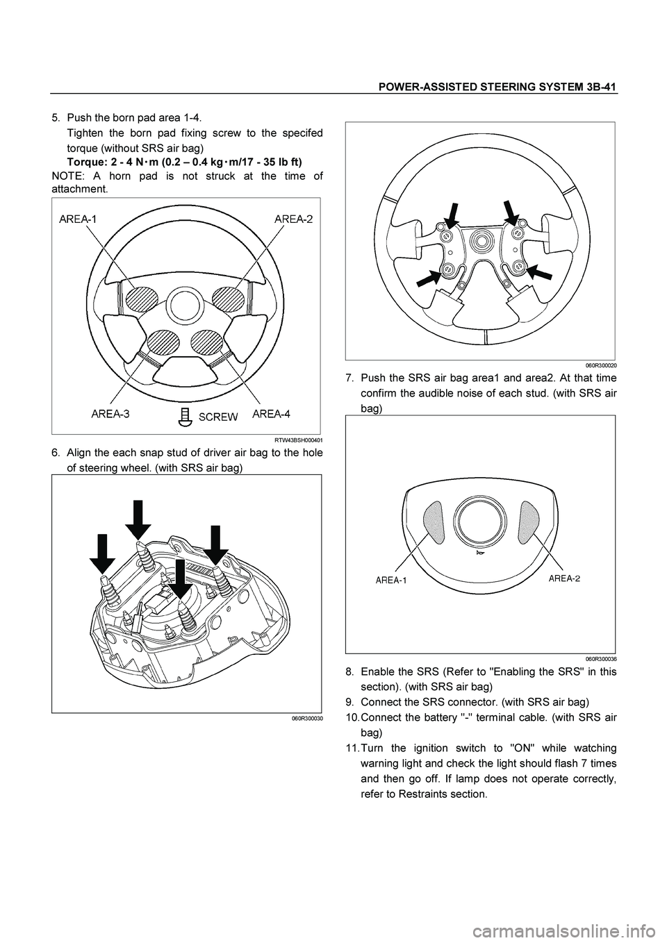
5. Push the born pad area 1-4.
Tighten the born pad fixing screw to the specifed
torque (without SRS air bag)
Torque: 2 - 4 N�
�� �m (0.2 – 0.4 kg�
�� �m/17 - 35 lb ft)
NOTE: A horn pad is not struck at the time o
f
attachment.
RTW43BSH000401
6. Align the each snap stud of driver air bag to the hole
of steering wheel. (with SRS air bag)
060R300030
060R300020
7. Push the SRS air bag area1 and area2. At that time
confirm the audible noise of each stud. (with SRS ai
r
bag)
060R300036
8. Enable the SRS (Refer to "Enabling the SRS" in this
section). (with SRS air bag)
9. Connect the SRS connector. (with SRS air bag)
10. Connect the battery "-" terminal cable. (with SRS ai
r
bag)
11. Turn the ignition switch to "ON" while watching
warning light and check the light should flash 7 times
and then go off. If lamp does not operate correctly,
refer to Restraints section.

RTW33BLF000701
Legend
(1) Pump Assembly
(2) Hose, Suction
(3) Hose, Flexible
(4) Bolt
(5) Connecto")

060R300030
060R300020
4. Push the SRS air bag area1 and area")
 Horn Lead
(2) SRS Connector
(3) Steering Wheel
(4) Steering Wheel Fixing Nut")