2004 ISUZU TF SERIES stop start
[x] Cancel search: stop startPage 2556 of 4264
6D3-2 STARTING AND CHARGING SYSTEM
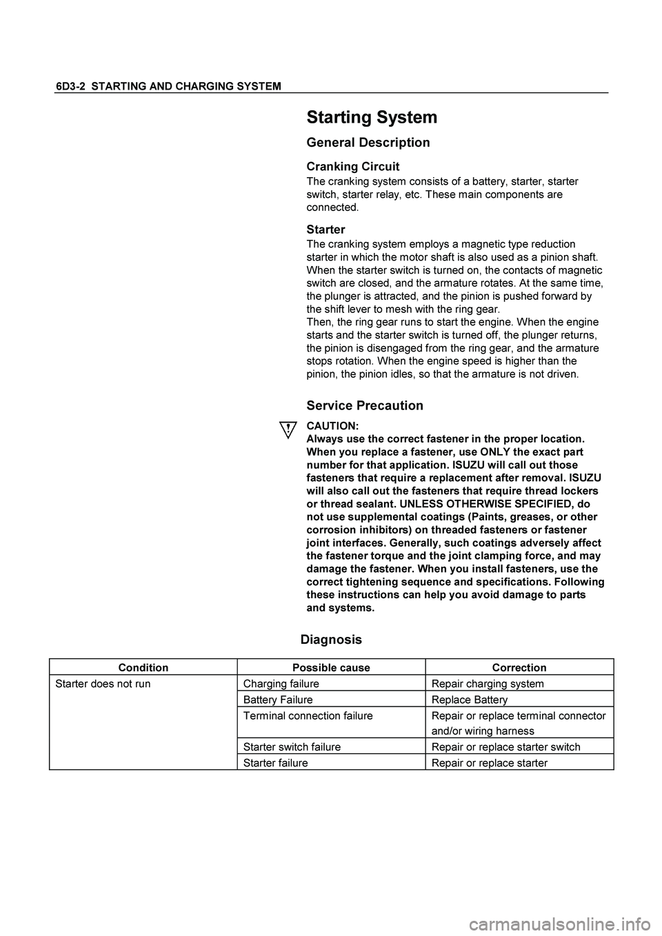
Starting System
General Description
Cranking Circuit
The cranking system consists of a battery, starter, starter
switch, starter relay, etc. These main components are
connected.
Starter
The cranking system employs a magnetic type reduction
starter in which the motor shaft is also used as a pinion shaft.
When the starter switch is turned on, the contacts of magnetic
switch are closed, and the armature rotates. At the same time,
the plunger is attracted, and the pinion is pushed forward by
the shift lever to mesh with the ring gear.
Then, the ring gear runs to start the engine. When the engine
starts and the starter switch is turned off, the plunger returns,
the pinion is disengaged from the ring gear, and the armature
stops rotation. When the engine speed is higher than the
pinion, the pinion idles, so that the armature is not driven.
Service Precaution
CAUTION:
Always use the correct fastener in the proper location.
When you replace a fastener, use ONLY the exact part
number for that application. ISUZU will call out those
fasteners that require a replacement after removal. ISUZU
will also call out the fasteners that require thread lockers
or thread sealant. UNLESS OTHERWISE SPECIFIED, do
not use supplemental coatings (Paints, greases, or other
corrosion inhibitors) on threaded fasteners or fastener
joint interfaces. Generally, such coatings adversely affect
the fastener torque and the joint clamping force, and may
damage the fastener. When you install fasteners, use the
correct tightening sequence and specifications. Following
these instructions can help you avoid damage to parts
and systems.
Diagnosis
Condition Possible cause Correction
Starter does not run Charging failure Repair charging system
Battery Failure Replace Battery
Terminal connection failure Repair or replace terminal connector
and/or wiring harness
Starter switch failure Repair or replace starter switch
Starter failure Repair or replace starter
Page 2562 of 4264
6D3-8 STARTING AND CHARGING SYSTEM
General On-Vehicle Inspection
The operating condition of charging system is indicated by the
charge warning lamp. The warning lamp comes on when the
starter switch is turned to "ON" position. The charging system
operates normally if the lamp goes off when the engine starts.
If the warning lamp shows abnormality or if undercharged or
overcharged battery condition is suspected, perform diagnosis
by checking the charging system as follows:
1. Check visually the belt and wiring connector.
2. With the engine stopped, turn the stator switch to "ON"
position and observe the warning lamp.
If lamp does not come on:
Disconnect wiring connector from generator, and ground
the terminal "L" on connector side.
If lamp comes on:
Repair or replace the generator.
Generator
Removal
1. Disconnect battery ground cable.
2. Move drive belt tensioner to loose side using wrench then
remove drive belt.
3. Disconnect terminal "B" wiring connector and connector.
4. Remove generator assembly.
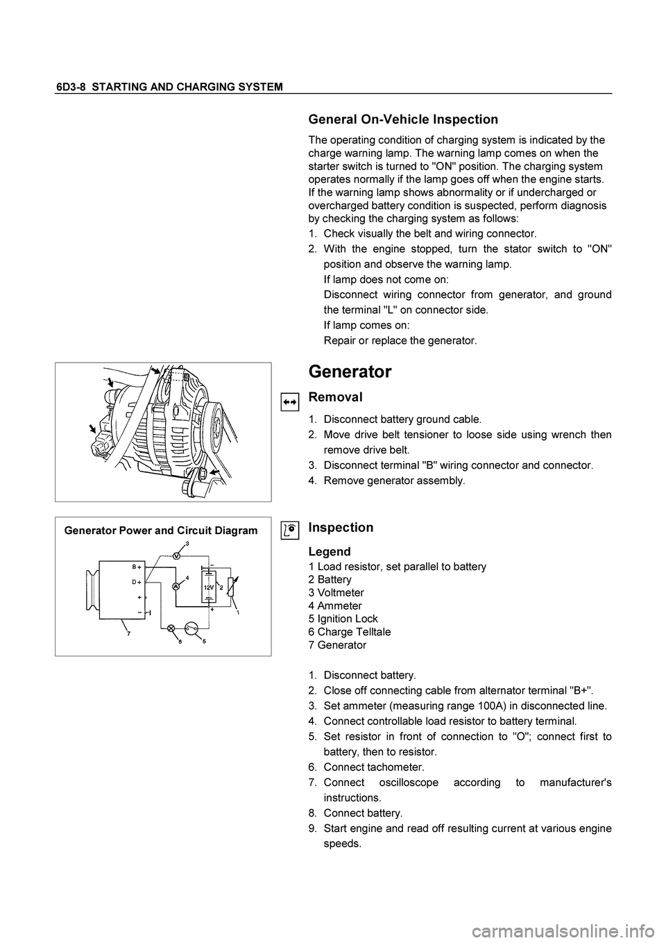
Generator Power and Circuit Diagram
Inspection
Legend
1 Load resistor, set parallel to battery
2 Battery
3 Voltmeter
4 Ammeter
5 Ignition Lock
6 Charge Telltale
7 Generator
1. Disconnect battery.
2. Close off connecting cable from alternator terminal "B+".
3. Set ammeter (measuring range 100A) in disconnected line.
4. Connect controllable load resistor to battery terminal.
5. Set resistor in front of connection to "O"; connect first to
battery, then to resistor.
6. Connect tachometer.
7. Connect oscilloscope according to manufacturer's
instructions.
8. Connect battery.
9. Start engine and read off resulting current at various engine
speeds.
Page 2567 of 4264
STARTING AND CHARGING SYSTEM 6D3-13
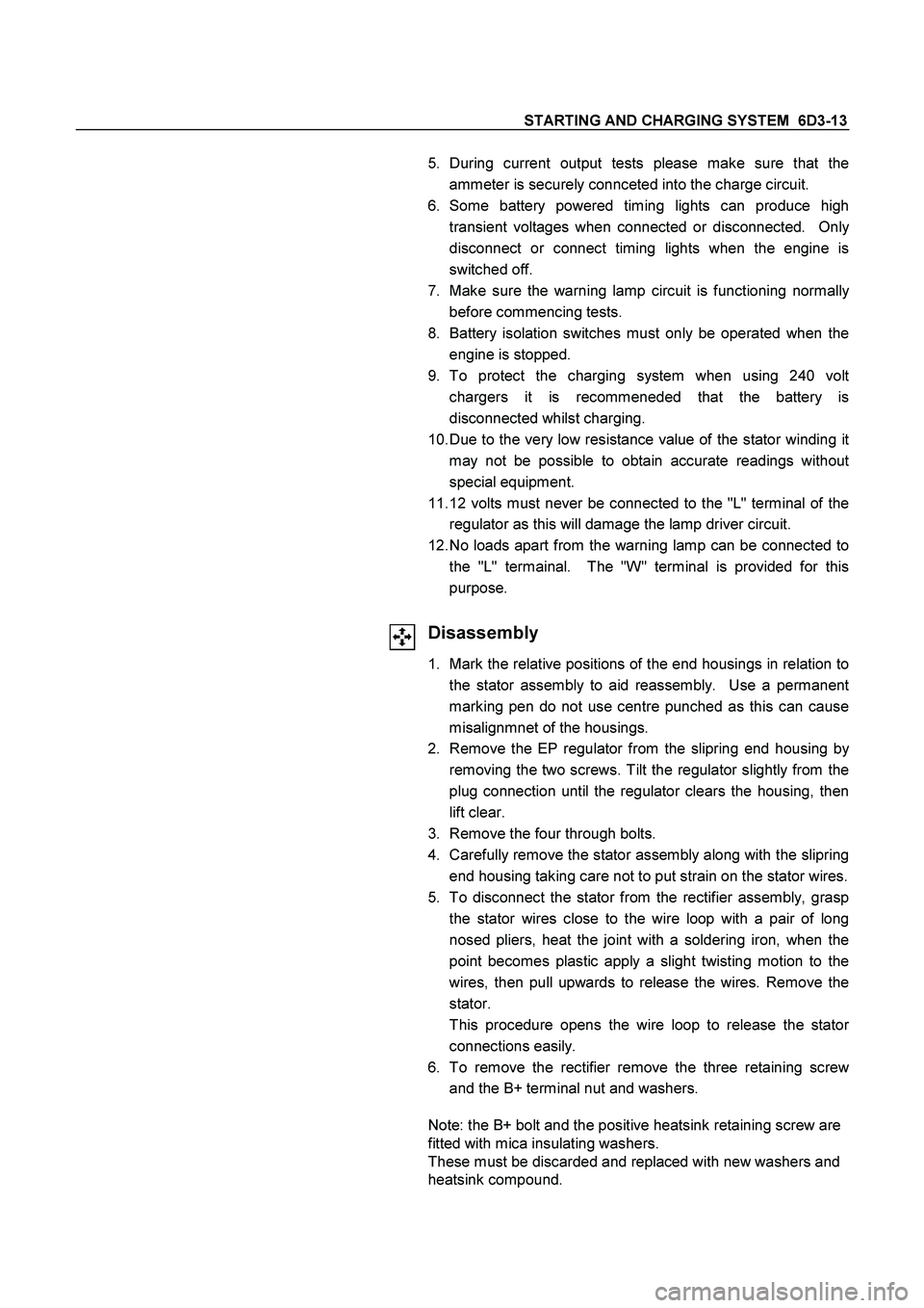
5. During current output tests please make sure that the
ammeter is securely connceted into the charge circuit.
6. Some battery powered timing lights can produce high
transient voltages when connected or disconnected. Onl
y
disconnect or connect timing lights when the engine is
switched off.
7. Make sure the warning lamp circuit is functioning normall
y
before commencing tests.
8. Battery isolation switches must only be operated when the
engine is stopped.
9. To protect the charging system when using 240 vol
t
chargers it is recommeneded that the battery is
disconnected whilst charging.
10. Due to the very low resistance value of the stator winding i
t
may not be possible to obtain accurate readings withou
t
special equipment.
11. 12 volts must never be connected to the "L" terminal of the
regulator as this will damage the lamp driver circuit.
12. No loads apart from the warning lamp can be connected to
the "L" termainal. The "W" terminal is provided for this
purpose.
Disassembly
1. Mark the relative positions of the end housings in relation to
the stator assembly to aid reassembly. Use a permanen
t
marking pen do not use centre punched as this can cause
misalignmnet of the housings.
2. Remove the EP regulator from the slipring end housing b
y
removing the two screws. Tilt the regulator slightly from the
plug connection until the regulator clears the housing, then
lift clear.
3. Remove the four through bolts.
4. Carefully remove the stator assembly along with the slipring
end housing taking care not to put strain on the stator wires.
5. To disconnect the stator from the rectifier assembly, grasp
the stator wires close to the wire loop with a pair of long
nosed pliers, heat the joint with a soldering iron, when the
point becomes plastic apply a slight twisting motion to the
wires, then pull upwards to release the wires. Remove the
stator.
This procedure opens the wire loop to release the stato
r
connections easily.
6. To remove the rectifier remove the three retaining scre
w
and the B+ terminal nut and washers.
Note: the B+ bolt and the positive heatsink retaining screw are
fitted with mica insulating washers.
These must be discarded and replaced with new washers and
heatsink compound.
Page 2608 of 4264
6E–32 ENGINE DRIVEABILITY AND EMISSIONS
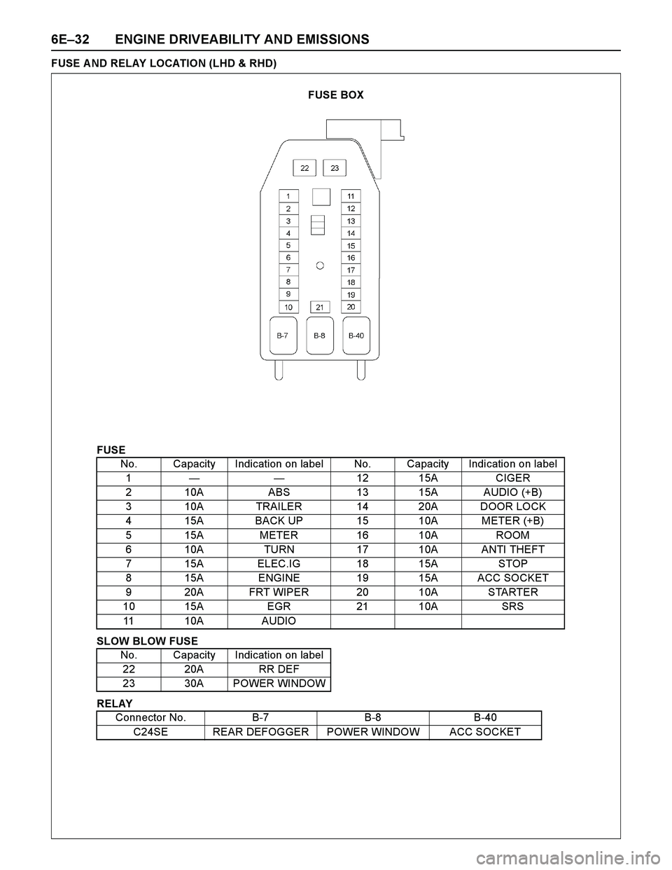
FUSE A ND RELAY LOCATION (LHD & RHD)
FUSE
SLOW BLOW FUSE
RELAYNo. Capacity Indication on label No. Capacity Indication on label
1——12 15A CIGER
2 10A ABS 13 15A AUDIO (+B)
3 10A TRAILER 14 20A DOOR LOCK
4 15A BACK UP 15 10A METER (+B)
5 15A METER 16 10A ROOM
6 10A TURN 17 10A ANTI THEFT
7 15A ELEC.IG 18 15A STOP
8 15A ENGINE 19 15A ACC SOCKET
9 20A FRT WIPER 20 10A STARTER
10 15A EGR 21 10A SRS
11 10A AUDIO
No. Capacity Indication on label
22 20A RR DEF
23 30A POWER WINDOW
Connector No. B-7 B-8 B-40
C24SE REAR DEFOGGER POWER WINDOW ACC SOCKET
FUSE BOX
Page 2648 of 4264
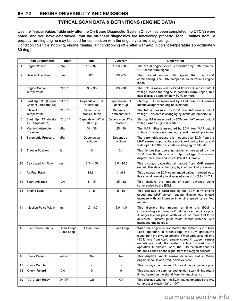
6E–72 ENGINE DRIVEABILITY AND EMISSIONS
TYPICAL SCAN DATA & DEFINITIONS (ENGINE DATA)
Use the Typical Values Table only after the On-Board Diagnostic System Check has been completed, no DTC(s) were
noted, and you have determined that the on-board diagnostics are functioning properly. Tech 2 values from a
properly-running engine may be used for comparison with the engine you are diagnosing.
Condition : Vehicle stopping, engine running, air conditioning off & after warm-up (Coolant temperature approx imately
80 deg.)
Tech 2 ParameterUnitsIdle2000rpmDescription
1 Engine Speed rpm775 - 8751950 - 2050 The actual engine speed is measured by ECM from the
CKP sensor 58X signal.
2 Desired Idle Speed rpm825800 - 850 The desired engine idle speed that the ECM
commanding. The ECM compensates for various engine
loa ds.
3 Engine Coolant
Te mpe rature°C or °F80 - 9080 - 90 The ECT is measured by ECM from ECT sensor output
voltage. When the engine is normally warm upped, this
data displays approximately 80 °C or more.
4 Sta rt Up ECT (Engine
Coolant Temperature)°C or °FDepends on ECT
a t start-upDepends on ECT
at sta rt-upStart-up ECT is measured by ECM from ECT sensor
output voltage when engine is started.
5Inta ke Air
Temperature °C or °FDe pe nds on
ambient tempDepends on
ambient tempThe IAT is mea sure d by ECM from IAT sensor o utput
voltage. This data is changing by intake air temperature.
6 Sta rt Up IAT (Inta ke
Air Temperature)°C or °FDepends on IAT at
sta rt-upDepends on IAT at
start-upStart-up IAT is me asured by ECM fro m IAT se nso r o utput
voltage when engine is started.
7 Manifold Absolute
Pre ssurekPa31 - 3625 - 30The MAP (kPa ) is me asure d by ECM fro m MAP o utput
voltage. This data is changing by inlet manifold pressure.
8 Barometric Pressure kPaDe pe nds on
altitudeDepends on
altitudeThe ba rome tric pre ssure is me asured by ECM fro m the
MAP sensor output voltage monitored during key up and
w ide o pe n thro ttle. This data is cha nging by a ltitude.
9 Throttle Position %02-4 Throttle position operating angle is measured by the
ECM from throttle position output voltage. This should
displa y 0% at idle a nd 99 - 100% at full throttle .
10 Calculated Air Flow g/s3.5 -4.508.0 - 10.0 This displays calculated air mount from MAP sensor
output. This data is changing by inlet manifold pressure .
11 Air Fuel Ratio14.6:114.6:1 This displays the ECM commanded value. In closed loop,
this should normally be displayed around 14.2:1 - 14.7:1.
12 Spark Advance °CA8 - 1525 - 32 This displays the amount of spark advance being
commanded by the ECM.
13 Engine Load %2 - 55 - 10 This displays is calculated by the ECM form engine
speed and MAF sensor reading. Engine load should
incre ase with an incre ase in engine spe ed or air flo w
amount.
14 Injection Pulse Width ms1.0 - 3.0 3.0 - 4.0 This displays the amount of time the ECM is
commanding each injector On during each engine cycle.
A lo nger injecto r pulse width will ca use more fuel to be
delivered. Injector pulse width should increase with
increased engine load.
15 Fuel System Status Open Loop/
Close LoopClo se Loo pClose Loop When the engine is first started the system is in “Open
Loop” operation. In “Open Loop”, the ECM ignores the
signal from the oxygen sensors. When various conditions
(ECT, time from start, engine speed & oxygen sensor
o utput) are me t, the syste m e nte rs “Closed Lo op”
o pera tio n. In “Close d Lo o p”, the ECM ca lculate s the air
fuel ratio based on the signal from the oxygen sensors.
16 Knock Present Yes/NoNoNo This displays knock sensor detection status. When
engine knock is occurred, displays "Yes".
17 Knock Counter-- This displays the number of knock during a ignition cycle.
18 Kno ck Reta rd °CA00 This displa ys the commande d ignitio n spa rk timing re tard
timing based on the signal from the knock sensor.
19 A/C Clutch Re la y On/OffOffOff This display s whe the r the ECM has co mma nde d the A/C
co mpre ssor clutch “On” or “Off”.
Page 2649 of 4264
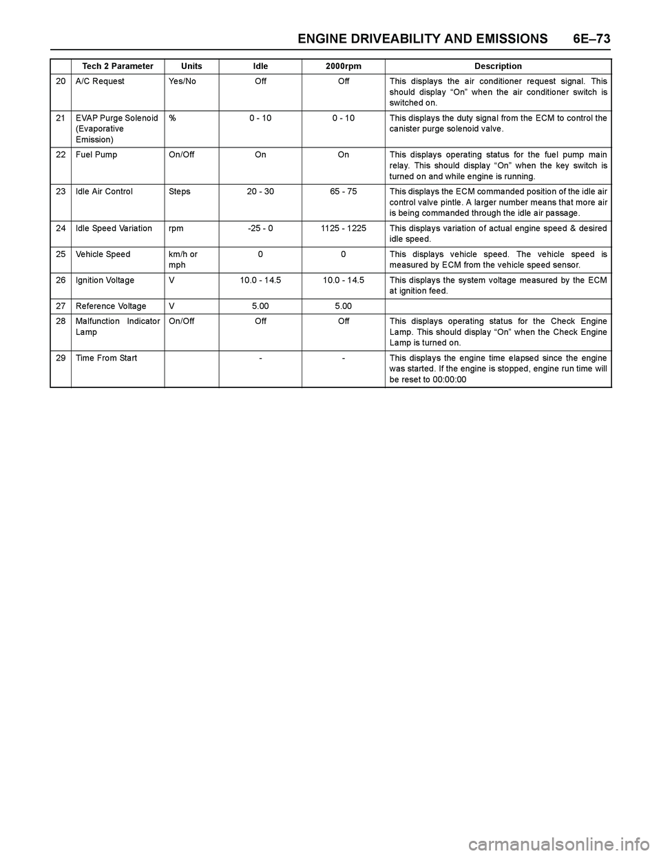
ENGINE DRIVEABILITY AND EMISSIONS 6E–73
20 A/C Reque st Ye s/NoOffOff This displays the air conditioner request signal. This
should display “On” whe n the air conditio ne r switch is
switche d o n.
21 EVAP Purge So le no id
(Evaporative
Emission)%0 - 100 - 10 This display s the duty signa l fro m the ECM to co ntrol the
ca nister purge so le no id v alve .
22 Fuel Pump On/OffOnOn This displays operating status for the fuel pump main
relay. This should display “On” when the key switch is
turned on and while engine is running.
23 Idle Air Contro l Ste ps20 - 3065 - 75 This displays the ECM commanded position of the idle air
control valve pintle. A larger number means that more air
is being commanded through the idle air passage.
24 Idle Speed Variation rpm-25 - 01125 - 1225 This displays variation of actual engine speed & desired
idle speed.
25 Vehicle Speed km/h or
mph00 This displays vehicle speed. The vehicle speed is
me asured by ECM from the v ehicle spe ed senso r.
26 Ignition Voltage V10.0 - 14.510.0 - 14.5 This displays the system voltage measured by the ECM
at ignition feed.
27 Reference Voltage V5.005.00
28 Ma lfunctio n Indicato r
La mpOn/OffOffOff This displays operating status for the Check Engine
La mp. This sho uld displa y “On” when the Check Engine
Lamp is turned on.
29Time From Start--This displays the engine time elapsed since the engine
was started. If the engine is stopped, engine run time will
be rese t to 00:00:00
Tech 2 ParameterUnitsIdle2000rpmDescription
Page 2650 of 4264
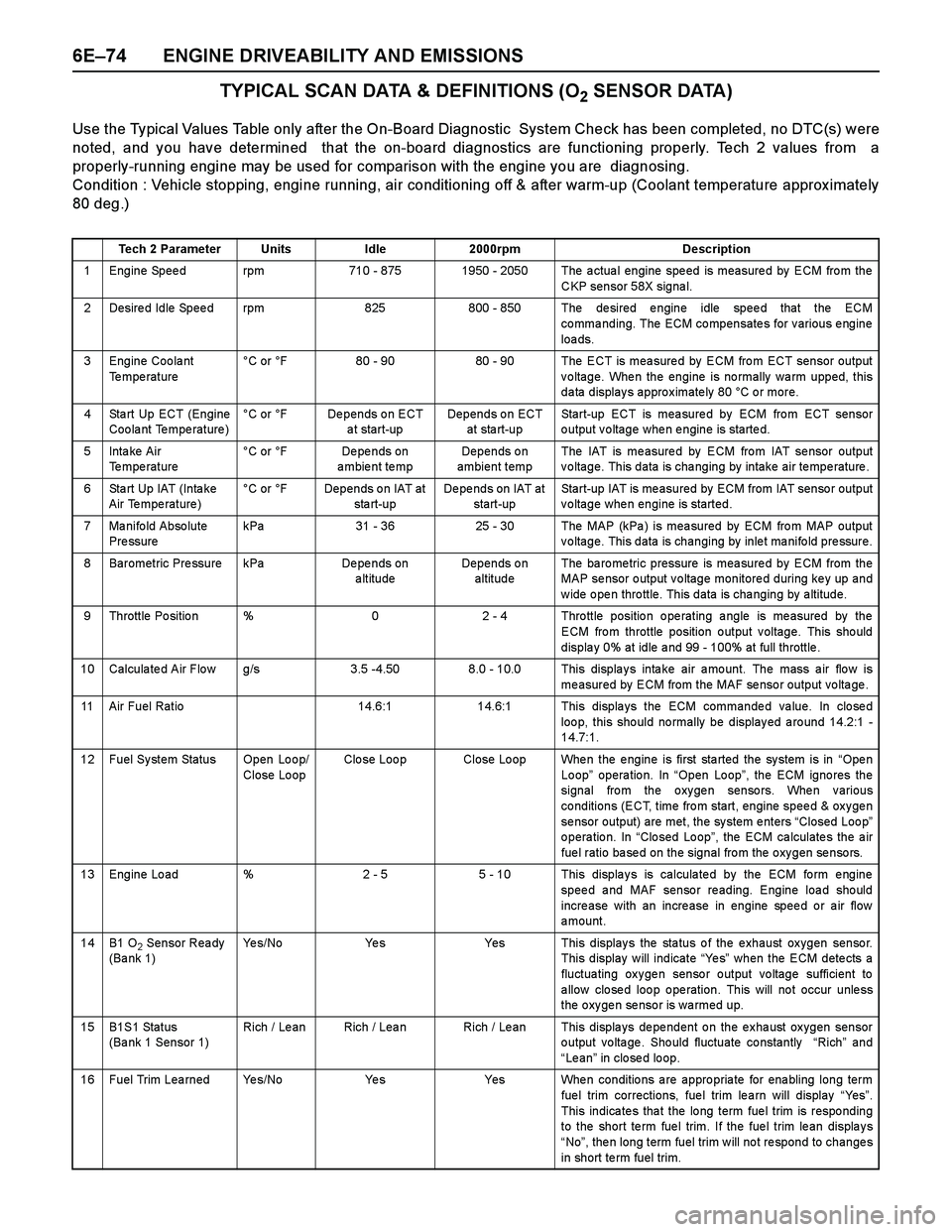
6E–74 ENGINE DRIVEABILITY AND EMISSIONS
TYPICAL SCAN DATA & DEFINITIONS (O2 SENSOR DATA)
Use the Typical Values Table only after the On-Board Diagnostic System Check has been completed, no DTC(s) were
noted, and you have determined that the on-board diagnostics are functioning properly. Tech 2 values from a
properly-running engine may be used for comparison with the engine you are diagnosing.
Condition : Vehicle stopping, engine running, air conditioning off & after warm-up (Coolant temperature approx imately
80 deg.)
Tech 2 ParameterUnitsIdle2000rpmDescription
1 Engine Speed rpm710 - 8751950 - 2050 The actual engine speed is measured by ECM from the
CKP sensor 58X signal.
2 Desired Idle Speed rpm825800 - 850 The desired engine idle speed that the ECM
commanding. The ECM compensates for various engine
loa ds.
3 Engine Coolant
Te mpe rature°C or °F80 - 9080 - 90 The ECT is measured by ECM from ECT sensor output
voltage. When the engine is normally warm upped, this
data displays approximately 80 °C or more.
4 Sta rt Up ECT (Engine
Coolant Temperature)°C or °FDepends on ECT
a t start-upDepends on ECT
at sta rt-upStart-up ECT is measured by ECM from ECT sensor
output voltage when engine is started.
5Inta ke Air
Temperature °C or °FDe pe nds on
ambient tempDepends on
ambient tempThe IAT is me asure d by ECM fro m IAT se nsor output
voltage. This data is changing by intake air temperature.
6 Sta rt Up IAT (Inta ke
Air Temperature)°C or °FDepends on IAT at
sta rt-upDepends on IAT at
start-upStart-up IAT is measured by ECM from IAT sensor output
voltage when engine is started.
7 Manifold Absolute
Pre ssurekPa31 - 3625 - 30The MAP (kPa ) is mea sured by ECM fro m MAP output
voltage. This data is changing by inlet manifold pressure.
8 Barometric Pressure kPaDe pe nds on
altitudeDepends on
altitudeThe ba ro me tric pressure is mea sure d by ECM from the
MAP se nsor o utput v o ltage monitore d during ke y up and
w ide o pe n thro ttle. This data is cha nging by a ltitude.
9 Throttle Position %02 - 4 Throttle position operating angle is measured by the
ECM from throttle position output voltage. This should
displa y 0% at idle a nd 99 - 100% at full throttle .
10 Calculated Air Flow g/s3.5 -4.508.0 - 10.0 This displays intake air amount. The mass air flow is
measured by ECM from the MAF sensor output voltage.
11 Air Fuel Ratio14.6:114.6:1 This displays the ECM commanded value. In closed
loo p, this sho uld no rmally be display ed a ro und 14.2:1 -
14.7:1.
12 Fuel System Status Open Loop/
Close LoopClo se Loo pClose Loop When the engine is first started the system is in “Ope n
Loop” operation. In “Open Loop”, the ECM igno res the
signal from the oxygen sensors. When various
conditions (ECT, time from start, engine speed & oxygen
sensor output) are met, the system enters “Closed Loop”
operation. In “Closed Loop”, the ECM calculates the air
fuel ratio based on the signal from the oxygen sensors.
13 Engine Load %2 - 55 - 10 This displays is calculated by the ECM form engine
speed and MAF sensor reading. Engine load should
increase with an increase in engine speed or air flow
amount.
14B1 O2 Sensor Ready
(Ba nk 1)Ye s / N oYe sYes This displays the status of the exhaust oxygen sensor.
This display will indicate “Ye s” when the ECM detects a
fluctuating oxygen sensor output voltage sufficient to
a llow clo se d loo p o pe ration. This will no t occur unle ss
the oxygen sensor is warmed up.
15B1S1 Status
(Bank 1 Sensor 1)Rich / Le anRich / LeanRich / Lean This displays dependent on the exhaust oxygen sensor
output voltage. Should fluctuate constantly “Rich” and
“Le an” in closed loop.
16 Fuel Trim Learned Yes/NoYe sYes When conditions are appropriate for enabling long term
fue l trim corrections, fue l trim le a rn will display “Ye s”.
This indica te s tha t the lo ng term fue l trim is respo nding
to the short te rm fue l trim. If the fue l trim le an displa y s
“No”, then long term fuel trim will not respond to changes
in short te rm fuel trim.
Page 2651 of 4264
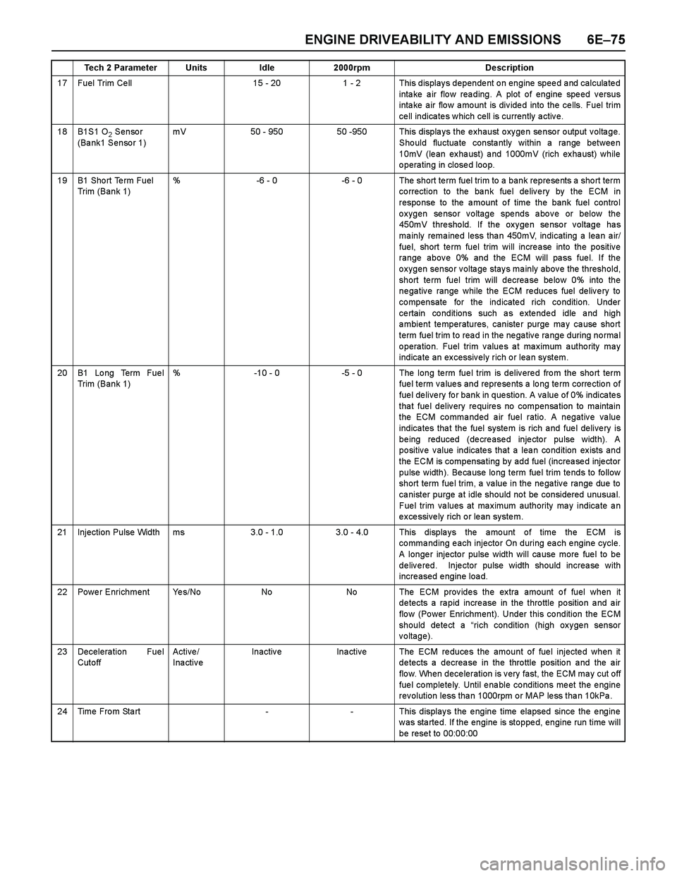
ENGINE DRIVEABILITY AND EMISSIONS 6E–75
17 Fuel Trim Ce ll15 - 201 - 2 This displays dependent on engine speed and calculated
intake air flow reading. A plot of engine speed versus
inta ke a ir flo w a mo unt is div ide d into the ce lls. Fuel trim
ce ll indica te s w hich cell is currently a ctiv e.
18B1S1 O2 Sensor
(Bank1 Sensor 1)mV50 - 95050 -950 This displays the exhaust oxygen sensor output voltage.
Should fluctuate constantly within a range between
10mV (lean exhaust) and 1000mV (rich exhaust) while
operating in closed loop.
19B1 Sho rt Te rm Fuel
Trim (Bank 1)%-6 - 0-6 - 0 The short term fuel trim to a bank represents a short term
co rrection to the ba nk fue l de liv e ry by the ECM in
response to the amount of time the bank fuel control
oxygen sensor voltage spends above or below the
450mV threshold. If the oxygen sensor voltage has
ma inly rema ine d less tha n 450mV, indicating a lea n a ir/
fue l, short te rm fuel trim will incre a se into the positiv e
range above 0% and the ECM will pass fuel. If the
oxygen sensor voltage stays mainly above the threshold,
short term fuel trim will decrease below 0% into the
negative range while the ECM reduces fuel delivery to
compensate for the indicated rich condition. Under
ce rtain co nditions such a s e xte nde d idle a nd high
ambient temperatures, canister purge may cause short
term fuel trim to rea d in the ne ga tiv e ra nge during no rma l
operation. Fuel trim values at maximum authority may
indica te an ex cessiv ely rich o r lea n sy stem.
20B1 Lo ng Term Fue l
Trim (Bank 1)%-10 - 0-5 - 0 The long te rm fue l trim is deliv ere d fro m the sho rt term
fuel term values and represents a long term correction of
fuel delivery for bank in question. A value of 0% indicates
that fuel delivery requires no compensation to maintain
the ECM commanded air fuel ratio. A negative value
indica tes tha t the fuel syste m is rich a nd fue l de live ry is
being reduced (decreased injector pulse width). A
positive value indicates that a lean condition exists and
the ECM is compensating by add fuel (increased injector
pulse width). Be ca use lo ng term fue l trim te nds to fo llow
short term fuel trim, a value in the negative range due to
canister purge at idle should not be considered unusual.
Fuel trim values at maximum authority may indicate an
excessively rich or lean system.
21Injection Pulse Widthms3.0 - 1.03.0 - 4.0 This displays the amount of time the ECM is
co mma nding e ach injecto r On during ea ch e ngine cycle.
A longer injector pulse width will cause more fuel to be
delivered. Injector pulse width should increase with
increased engine load.
22Power EnrichmentYe s / N oNoNo The ECM provides the extra amount of fuel when it
detects a rapid increase in the throttle position and air
flo w (Po wer Enrichment). Under this co ndition the ECM
should detect a “rich condition (high oxygen sensor
voltage).
23Decelera tion Fue l
Cut o ff Active /
InactiveInactiveIna ctiveThe ECM reduces the amount of fuel injected when it
detects a decrease in the throttle position and the air
flow. When deceleration is very fast, the ECM may cut off
fue l co mple te ly. Until e na ble co nditions me et the e ngine
rev olution less tha n 1000rpm o r MAP le ss tha n 10kPa .
24Time From Start--This displays the engine time elapsed since the engine
w as sta rte d. If the engine is stoppe d, engine run time will
be rese t to 00:00:00
Tech 2 ParameterUnitsIdle2000rpmDescription