Page 3065 of 4264
HEATER AND AIR CONDITIONING 1-55
Important Operations – Removal
2. Instrument Panel Assembly and Cross Beam.
Refer to INSTRUMENT PANEL in CAB section.
4. Evaporator or Duct
Refer to “EVAPORATOR” or “DUCT” in this section.
Important Operation - Installation
2. Instrument Panel Assembly and Cross Beam
Adjust the heater control cables.
Refer to "CONTROL LEVER ASSEMBLY" in this section.
Page 3068 of 4264
1-58 HEATER AND AIR CONDITIONING
Important Operations - Removal
2. Instrument Panel Assembly and Cross Beam.
Refer to INSTRUMENT PANEL in CAB section.
4. Evaporator or Duct
Refer to “EVAPORATOR” or “DUCT” in this section.
Important Operation - Installation
2. Instrument Panel Assembly and Cross Beam
Adjust the heater control cables.
Refer to "CONTROL LEVER ASSEMBLY" in this section.
Page 3076 of 4264
1-66 HEATER AND AIR CONDITIONING
Important Operation - Installation
2. Instrument Panel Assembly and Cross Beam
Refer to “INSTRUMENT PANEL” in CAB section.
4. Evaporator or Duct
Refer to “EVAPORATOR” or “DUCT” in this section.
Important Operation - Installation
2. Instrument Panel Assembly and Cross Beam
Adjust the heater control cables.
Refer to “CONTOROL LEVER ASSEMBLY” in this section.
Page 3078 of 4264
1-68 HEATER AND AIR CONDITIONING
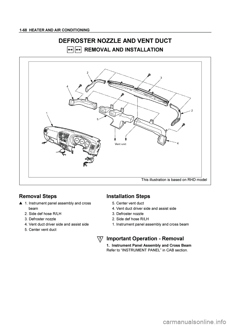
DEFROSTER NOZZLE AND VENT DUCT
REMOVAL AND INSTALLATION
This illustration is based on RHD model
Removal Steps
� 1. Instrument panel assembly and cross
beam
2. Side def hose R/LH
3. Defroster nozzle
4. Vent duct driver side and assist side
5. Center vent duct
Installation Steps
5. Center vent duct
4. Vent duct driver side and assist side
3. Defroster nozzle
2. Side def hose R/LH
1. Instrument panel assembly and cross beam
Important Operation - Removal
1. Instrument Panel Assembly and Cross Beam
Refer to “INSTRUMENT PANEL ” in CAB section.
Page 3079 of 4264
HEATER AND AIR CONDITIONING 1-69
REAR HEATER DUCT
REMOVAL AND INSTALLATION
This illustration is based on RHD model
RTW410LF001301
Disassembly Steps
1. Front seat assembly (RH/LH)
� Refer to SECTION 10 “FRONT SEAT”
2. Rear floor console
�
Refer to SECTION 10 “FLOOR
CONSOLE”
3. Front floor console (A/T, M/T Model)
�
Refer to SECTION 10 “FLOOR
CONSOLE”
4. Sill plate (RH/LH)
� Refer to SECTION 10 “INTERIOR
TRIM PANELS”
5. Dash side trim cover (RH/LH)
6. Carpet
7. Clip
8. Rear Heater duct (RH/LH)
9. Rear Heater duct center
Reassembly Steps
9. Rear heater duct center
8. Rear heater duct (RH/LH)
7. Clip
6. Carpet
5. Dash side trim cover (RH/LH)
4. Sill plate (RH/LH)
�
Refer to SECTION 10 “INTERIOR
TRIM PANELS”
3. Front floor console (A/T, M/T Model)
� Refer to SECTION 10 “FLOOR
CONSOLE”
2. Rear floor console
�
Refer to SECTION 10 “FLOOR
CONSOLE”
1. Front seat assembly (RH/LH)
�
Refer to SECTION 10 “FRONT SEAT”
Page 3081 of 4264
HEATER AND AIR CONDITIONING 1-71
Important Operation - Removal
2. Instrument Panel Driver Lower Cover
Refer to “INSTRUMENT PANEL” in CAB section.
RTW310SH000101
4. Control Cables
Disconnect control cables at each unit side.
5. Center Cluster
Refer to “INSTRUMENT PANEL” in CAB section.
Page 3085 of 4264
HEATER AND AIR CONDITIONING 1-75
Important Operation - Removal
1. Control lever assembly
Refer to “CONTROL LEVER ASSEMBLY” in this section.
2. Illumination Bulb
To remove the illumination bulb, insert an ordinary screwdriver
into the slot (B) at the back of the bulb. Turn the bulb
counterclockwise and pull it free.
Page 3093 of 4264

HEATER AND AIR CONDITIONING 1-83
AIR CONDITIONING CYCLE TROUBLESHOOTING
TROUBLE POSSIBLE CAUSE CORRECTION
No cooling or
insufficient
cooling
1. Magnetic clutch does not run
��
Refer to “MAGNETIC CLUTCH”
troubleshooting in this section
2. Compressor is not rotating properly
��Drive belt loosened or broken ��
Adjust the drive belt to the specified
tension or replace the drive belt
��Magnetic clutch face is not clean and
slips ��Clean the magnetic clutch face or replace
��
Incorrect clearance between magnetic
drive plate and pulley ��
Adjust the clearance (Refer to
“COMPRESSOR OVERHAUL”
��
Compressor oil leaks from shaft seal or
shell ��
Replace the compressor
��
Compressor seized ��
Replace the compressor
3. Insufficient or excessive charge of
refrigerant ��
Discharge and recover refrigerant.
Recharge to specified amount.
4. Leaks in the refrigerant system
��
Check refrigerant system for leaks and
repair as necessary
Discharge and recover refrigerant.
Recharge to specified amount.
5. Condenser clogged or insufficient radiation
��Clean the condenser or replace as
necessary
��
Check radiator or condenser fan function
6. Temperature control link unit of the heater
unit defective ��
Repair the link unit
7. Unsteady operation due to foreign
substance in expansion valve ��
Replace the expansion valve
8. Poor operation of electronic thermostat
��
Check electronic thermostat and replace
as necessary
Insufficient
velocity
of cooling air
1. Evaporator clogged or frosted
��
Check evaporator core and replace or
clean the core
2. Air leaking from cooling unit or air duct
��Check evaporator and duct connection,
then repair as necessary
3. Blower motor does not rotate prop-erly
��
Refer to “FAN CONTROL KNOB (FAN
SWITCH)” troubleshooting in this section
* For the execution of the charging and discharging operation in the table above, refer to the “RECOVERY,
RECYCLING, EVACUATING AND CHARGING” in this section.


")

