Page 4231 of 4264
 7A4-57
11CASE-AY01
5. Oil seal
Using a screwdriver, remove the oil seal from the
transmission case.
Inspection
2 – 4 brake drive plate
Measure the 2-")
UNIT REPAIR (JR405E) 7A4-57
11CASE-AY01
5. Oil seal
Using a screwdriver, remove the oil seal from the
transmission case.
Inspection
2 – 4 brake drive plate
Measure the 2-4 brake drive plate facing thickness at 3
points and calculate the average value.
If the average value is less than the specified limit, the 2-4
brake drive plate must be replaced.
2 – 4 brake drive plate facing thickness:
Standard = 2.0 mm (0.079 in)
Limit = 1.8 mm (0.071 in)
Low and reverse brake drive plate
Measure the low and reverse brake drive plate facing
thickness at 3 points and calculate the average value.
If the average value is less than the specified limit, the lo
w
and reverse drive plate must be replaced.
Low and reverse brake drive plate facing thickness:
Standard = 2.0 mm (0.079 in)
Limit = 1.8 mm (0.071 in)
2 – 4 brake return spring
� Check the number of effective 2-4 brake return spring
coils.
Effective return spring coils (Standard): 10.2
� Measure the 2-4 brake return spring outside diameter,
free length, and linear diameter.
If any of the measured values exceed the specified limit,
the 2-4 brake return spring must be replaced.
2 – 4 brake return spring measurements (Standard):
Outside diameter = 6.9 mm (0.272 in)
Free length = 22.5 mm (0.886 in)
Linear diameter = 1.1 mm (0.043 in)
Low and reverse brake return spring
� Check the number of effective low and reverse brake
return spring coils.
Effective return spring coils (standard): 4.8
� Measure the low and reverse brake return spring outside
diameter, free length, and linear diameter.
If any of the measured values exceed the specified limit,
the low and reverse return spring must be replaced.
Low and reverse brake return spring measurements
(Standard):
Outside diameter = 11.2 mm (0.441 in)
Page 4232 of 4264
7A4-58 UNIT REPAIR (JR405E)
Free length = 22.3 mm (0.878 in)
Linear diameter = 1.1 mm (0.043 in)
12CASE-AY06
Reassembly steps
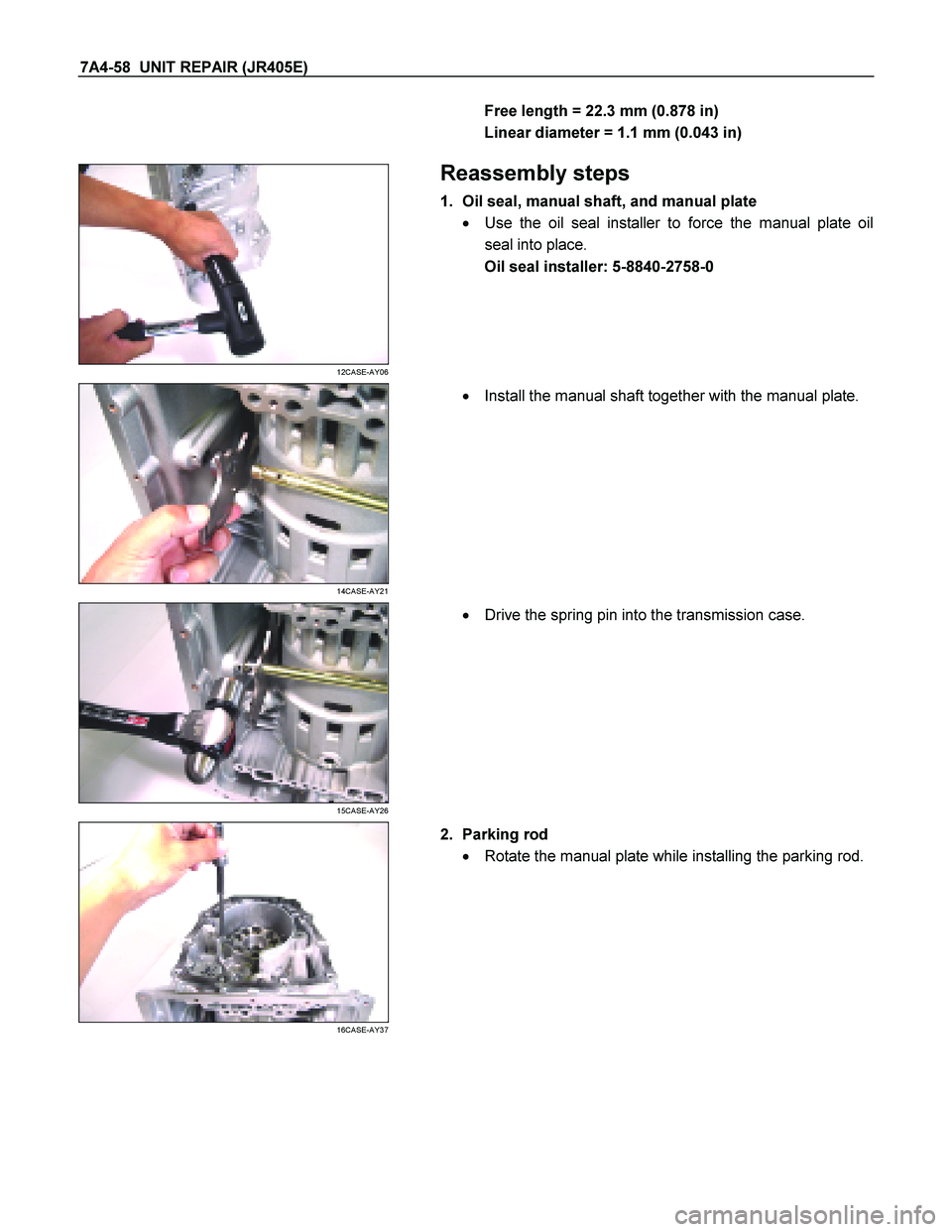
1. Oil seal, manual shaft, and manual plate
� Use the oil seal installer to force the manual plate oil
seal into place.
Oil seal installer: 5-8840-2758-0
14CASE-AY21
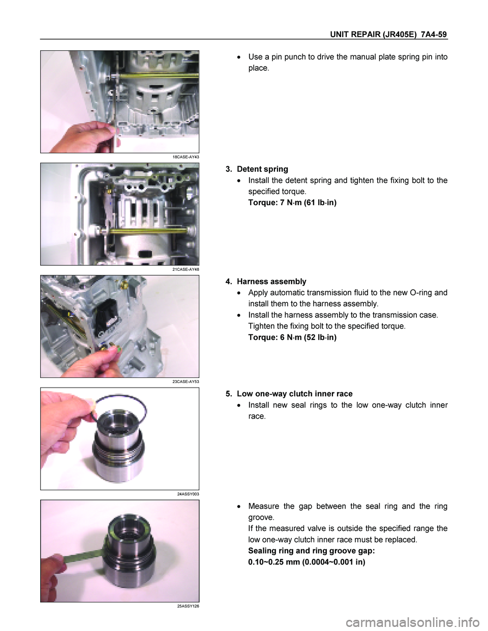
�
Install the manual shaft together with the manual plate.
15CASE-AY26
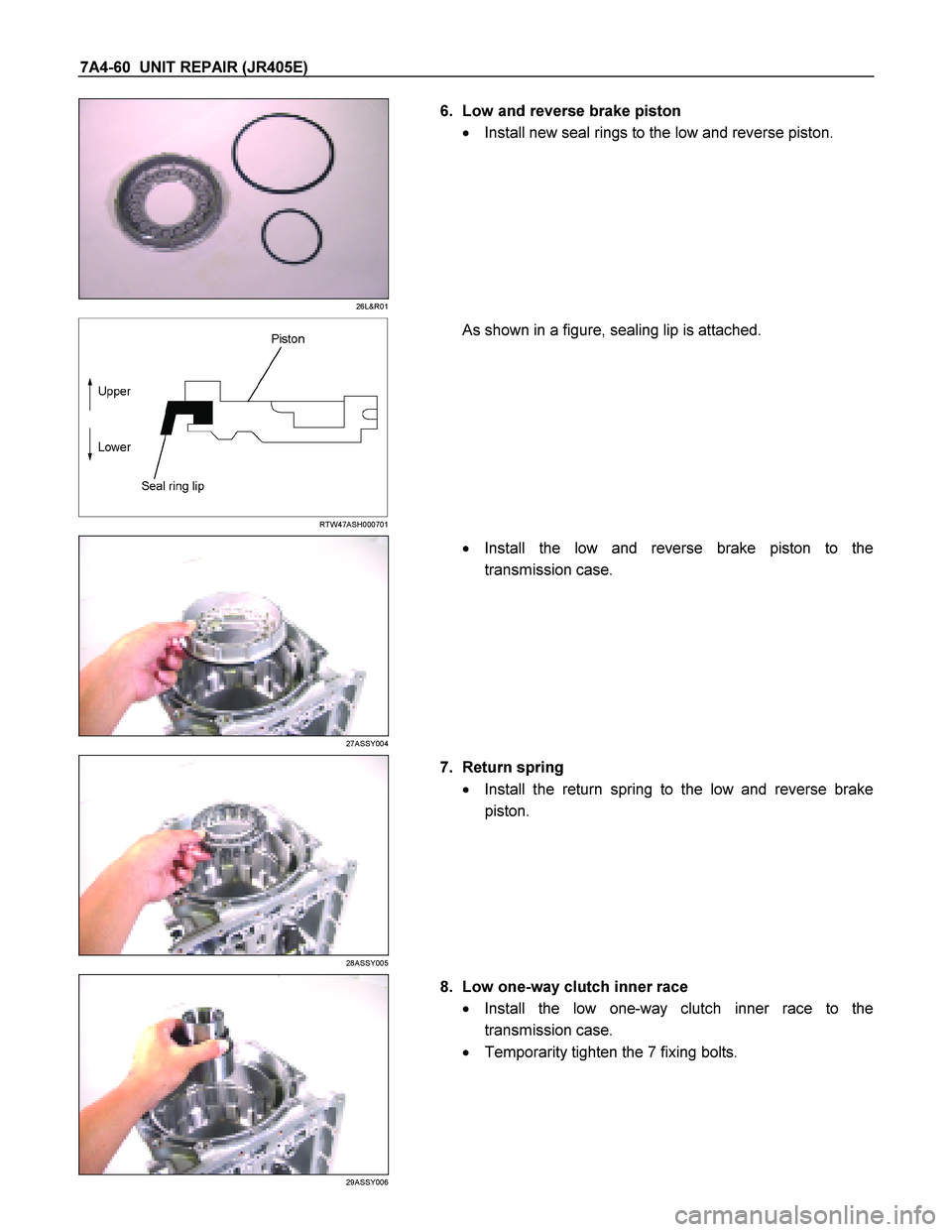
�
Drive the spring pin into the transmission case.
16CASE-AY37
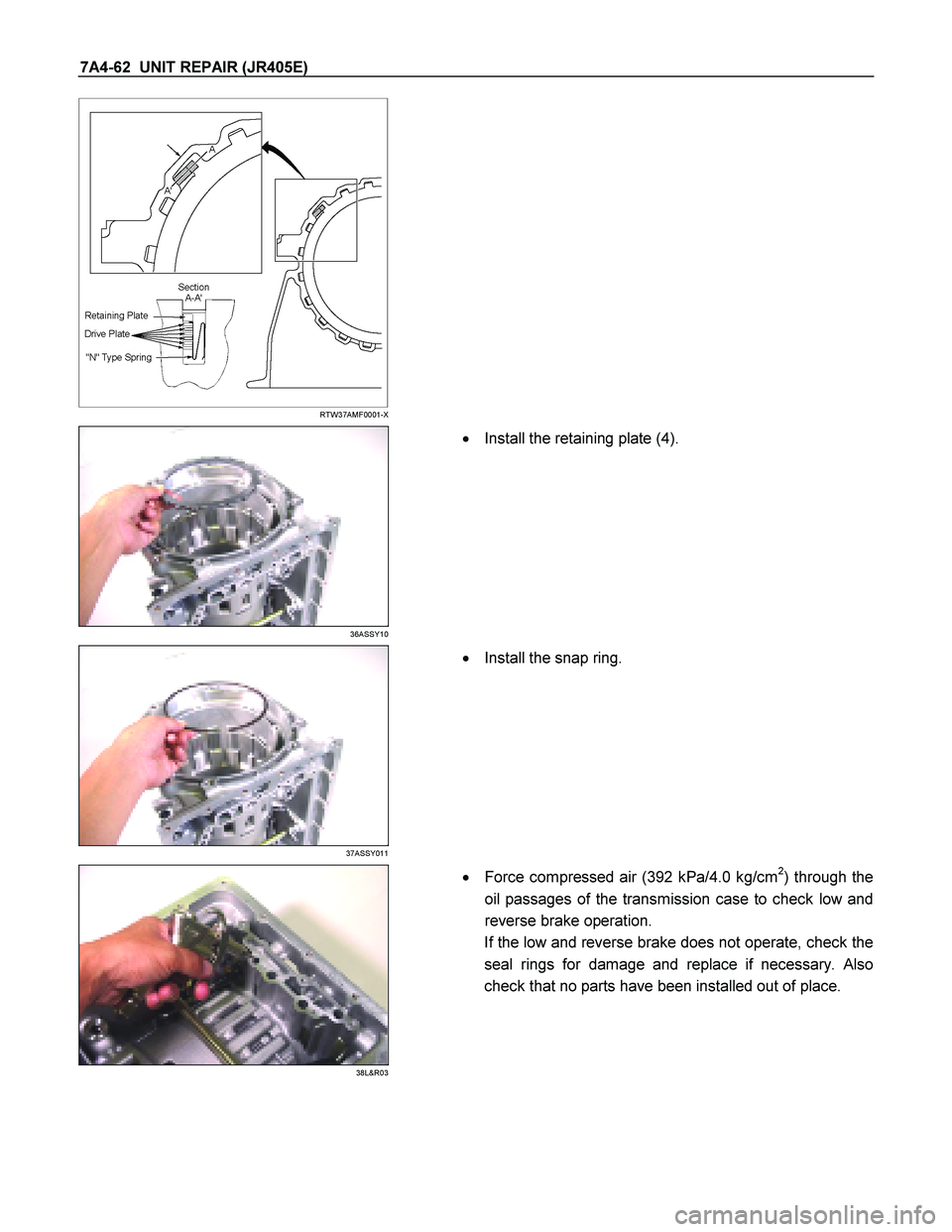
2. Parking rod
� Rotate the manual plate while installing the parking rod.
Page 4233 of 4264
UNIT REPAIR (JR405E) 7A4-59
18CASE-AY43
�
Use a pin punch to drive the manual plate spring pin into
place.
21CASE-AY48
3. Detent spring
� Install the detent spring and tighten the fixing bolt to the
specified torque.
Torque: 7 N �
��
�
m (61 Ib �
��
�
in)
23CASE-AY53
4. Harness assembly
� Apply automatic transmission fluid to the new O-ring and
install them to the harness assembly.
� Install the harness assembly to the transmission case.
Tighten the fixing bolt to the specified torque.
Torque: 6 N �
��
�
m (52 Ib �
��
�
in)
24ASSY003
5. Low one-way clutch inner race
� Install new seal rings to the low one-way clutch inne
r
race.
25ASSY126
�
Measure the gap between the seal ring and the ring
groove.
If the measured valve is outside the specified range the
low one-way clutch inner race must be replaced.
Sealing ring and ring groove gap:
0.10~0.25 mm (0.0004~0.001 in)
Page 4234 of 4264
7A4-60 UNIT REPAIR (JR405E)
26L&R01
6. Low and reverse brake piston
� Install new seal rings to the low and reverse piston.
RTW47ASH000701
As shown in a figure, sealing lip is attached.
27ASSY004
�
Install the low and reverse brake piston to the
transmission case.
28ASSY005
7. Return spring
� Install the return spring to the low and reverse brake
piston.
29ASSY006
8. Low one-way clutch inner race
� Install the low one-way clutch inner race to the
transmission case.
� Temporarity tighten the 7 fixing bolts.
Page 4236 of 4264
7A4-62 UNIT REPAIR (JR405E)
RTW37AMF0001-X
36ASSY10
�
Install the retaining plate (4).
37ASSY011
�
Install the snap ring.
38L&R03
�
Force compressed air (392 kPa/4.0 kg/cm2) through the
oil passages of the transmission case to check low and
reverse brake operation.
If the low and reverse brake does not operate, check the
seal rings for damage and replace if necessary. Also
check that no parts have been installed out of place.
Page 4237 of 4264
UNIT REPAIR (JR405E) 7A4-63
39L&R04
249L300003
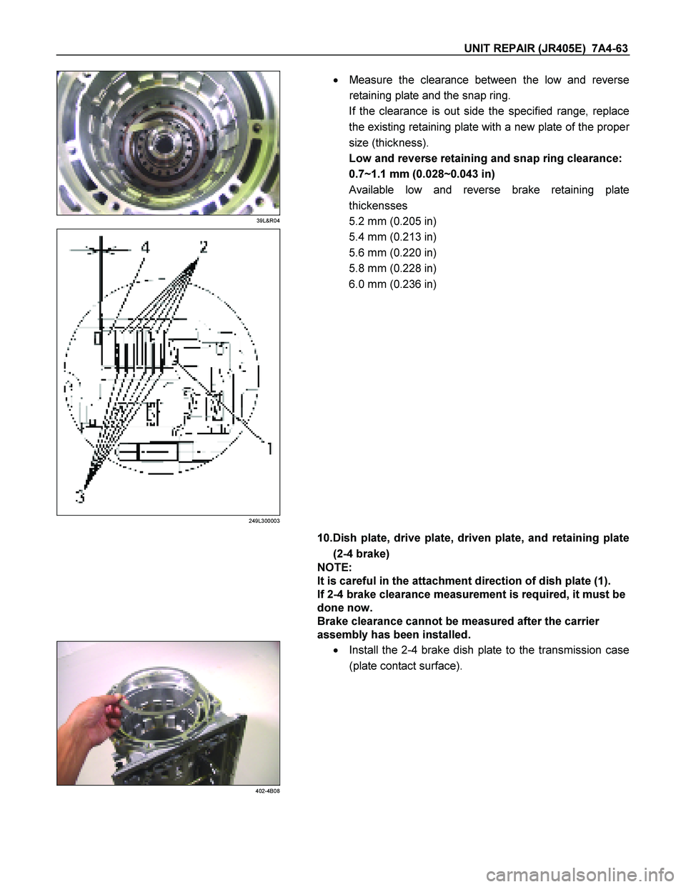
�
Measure the clearance between the low and reverse
retaining plate and the snap ring.
If the clearance is out side the specified range, replace
the existing retaining plate with a new plate of the prope
r
size (thickness).
Low and reverse retaining and snap ring clearance:
0.7~1.1 mm (0.028~0.043 in)
Available low and reverse brake retaining plate
thickensses
5.2 mm (0.205 in)
5.4 mm (0.213 in)
5.6 mm (0.220 in)
5.8 mm (0.228 in)
6.0 mm (0.236 in)
10.Dish plate, drive plate, driven plate, and retaining plate
(2-4 brake)
NOTE:
It is careful in the attachment direction of dish plate (1).
If 2-4 brake clearance measurement is required, it must be
done now.
Brake clearance cannot be measured after the carrier
assembly has been installed.
402-4B08
�
Install the 2-4 brake dish plate to the transmission case
(plate contact surface).
Page 4238 of 4264
7A4-64 UNIT REPAIR (JR405E)
412-4B09
�
Install the drive plate, driven plate, and the retaining
plate.
422-4B10
432-4B11
442-4B12
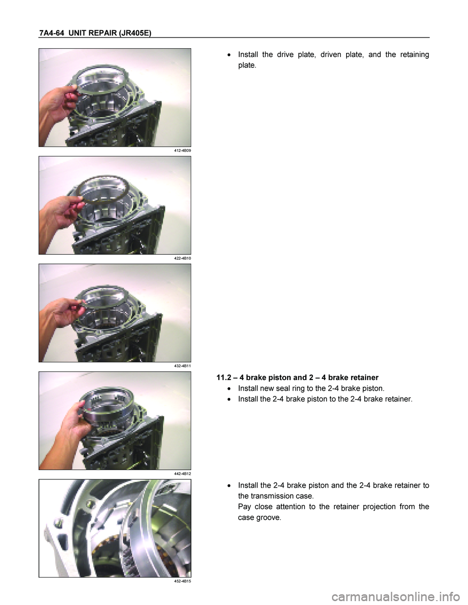
11.2
– 4 brake piston and 2 – 4 brake retainer
� Install new seal ring to the 2-4 brake piston.
� Install the 2-4 brake piston to the 2-4 brake retainer.
452-4B15
�
Install the 2-4 brake piston and the 2-4 brake retainer to
the transmission case.
Pay close attention to the retainer projection from the
case groove.
Page 4239 of 4264
 7A4-65
472-4B17
�
Install the spring compressor to the transmission case.
Spring compressor: 5-8840-2764-0
NOTE:
Be sure that the spring compressor is perfectl")
UNIT REPAIR (JR405E) 7A4-65
472-4B17
�
Install the spring compressor to the transmission case.
Spring compressor: 5-8840-2764-0
NOTE:
Be sure that the spring compressor is perfectly centered
(an off-center special tool will damage the return spring).
� Use the spring compressor to force the 2-4 brake
retainer.
482-4B18
NOTE:
To avoid damaging the return spring, apply as little force
as possible to the 2-4 brake retainer.
� Install the snap ring.
492-4B22
�
Force compressed air (392 kPa/4.0 kg/cm2) through the
oil passages of the transmission case to operate and
break-in the 2-4 brake.
502-4B19
�
Measure the clearance between the 2-4 brake retainer
and the retaining plate.
If the clearance is outside the specified range, replace
the existing brake retainer with a new one of the prope
r
size (thickness).
2 – 4 brake retainer and retaining plate clearance:
1.0~1.4 mm (0.039~0.055 in)
Available 2-4 brake retaining plate thicknesses
5.4 mm (0.213 in)
5.6 mm (0.220 in)
5.8 mm (0.228 in)
6.0 mm (0.236 in)
6.2 mm (0.244 in)
6.4 mm (0.252 in)
� Use the spring compressor to release the 2-4 brake.