Page 3300 of 4264
11A-14 IMMOBILIZER SYSTEM
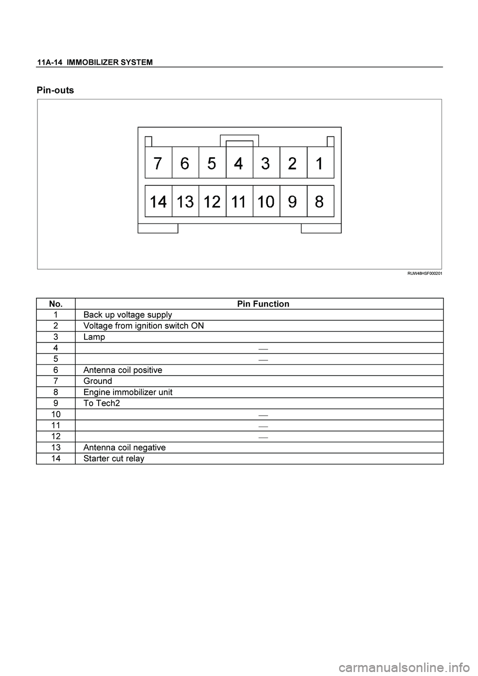
Pin-outs
RUW48HSF000201
No. Pin Function
1 Back up voltage supply
2 Voltage from ignition switch ON
3 Lamp
4
�
5
�
6 Antenna coil positive
7 Ground
8 Engine immobilizer unit
9 To Tech2
10
�
11 �
12
�
13 Antenna coil negative
14 Starter cut relay
Page 3301 of 4264
IMMOBILIZER SYSTEM 11A-15
Immobilizer coil (Antenna)
Immobilizer coil is install in order that ICU may check
the security code memorized by the transponder (key).
RUW38HSH000301
Transponder (Key)
Transponder is installed in the inside of a key.
Transponder has memorized the security code of a
immobilizer system.
LTW3BASH000101
Legend
(1) Transponder (Key)
Check engine lamp
Check engine lamp displays failure or a system
operation of a immobilizer system by flash of a lamp.
LTW3BASH000201
Engine control module (ECM)
ECM will stop engine, if it communicates with ICU and
abnormalities are detected by a key and the immobilize
r
system.
LTW3BASH000301
Legend
(1) ECM (6VE1 engine)
(2) ECM (C24SE engine)
(3) ECM (4JH1-TC engine)
Page 3317 of 4264

IMMOBILIZER SYSTEM 11A-31
Diagnostic procedure
�
Once the cause of DTC is repaired or gone,
engine can be operated normally, and present
DTC becomes history code.
�
History code is canceled by no repeat failure on 25
consequence ignition key on afterward.
�
History code cannot be canceled by batter
y
connector disconnected.
Clearing Diagnostic Trouble Codes
IMPORTANT:
Do not clear DTCs unless directed to do
so by the service information provided for each
diagnostic procedure. When DTCs are cleared, the
Failure Record data which may help diagnose an
intermittent fault will also be erased from memory.
Verifying Vehicle Repair
Verification of vehicle repair will be more
comprehensive for vehicles with immobilizer system
diagnostic. Following a repair, the technician should
perform the following steps:
1.
Review and record the Fail Records for the DTC
which has been diagnosed.
2.
Clear DTC(s).
3.
Operate the vehicle within conditions noted in the
Fail Records.
4.
Monitor the DTC status information for the DTC
which has been diagnosed until the diagnostic test
associated with that DTC runs.
Following these steps are very important in verifying
repairs on immobilizer systems. Failure to follow these
steps could result in unnecessary repairs.
Diagnostic Aids
Check the condition for system parts.
�
Installation condition, poor connection, damage,
system parts malfunction. Harness, Fuse, Relay,
Immobilizer coil (antenna), Key, Meter, Immobilize
r
control unit (ICU), Engine control module (ECM).
NOE: Breakage of immobilizer fuse does not operate
immobilizer system. Check engine lamp flashes at this
time.
Check the Electro-Magnetic Interference (EMI)
�
Location of vehicle check
Move the vehicle to a new location and perform
the check again.
�
Non-OEM Parts.
Switch is "OFF" or remove the Non-OEM parts and
perform the check again.
�
Other
Remove the accessory and another key from key.
Check the other items.
�
Battery voltage is low.
�
Immobilizer programming functions.
Must be programmed immobilizer system.
�
Registration for security code, immobilizer control
unit parts number.
�
Key switch operation.
Immobilizer system may detect a history DTC b
y
the timing of ON-OFF of a key switch.
�
Active the immobilizer system.
�
Keyless entry system is malfunction.
�
Anti theft system is malfunction.
Check the operation
Check the operation "Lock / unlock" by using transmitte
r
(key) on the vehicle.
Page 3318 of 4264
 list with ECM
�
�� � Immobilizer Control Unit (ICU)
DTC
Description Note
B0001
REPLACE ELECTRONIC CONTROL UNIT
(ECU) (IMMOBILIZER FAULT")
11A-32 IMMOBILIZER SYSTEM
Diagnostic Trouble Code (DTC) list with ECM
�
�� � Immobilizer Control Unit (ICU)
DTC
Description Note
B0001
REPLACE ELECTRONIC CONTROL UNIT
(ECU) (IMMOBILIZER FAULT) This error code appears if a RAM /ROM Error was
detected or the EEPROM is defect.
B0002 IMMOBILIZER NOT PROGRAMMED Immobilizer control unit is not programmed.
B0003 TRANSPONDER KEY PROBLEM �
Reading of Transponder information failed with ignition
on transponder has a fault.
�
Hardware fault in reading circuit.
B0004
IMMOBILIZER COIL CIRCUIT (ANTENNA
COIL FAULT) Immobilizer coil has a fault.
B0005 COMMUNICATION LINE W VOLTAGE LOW Short circuit to ground or open circuit.
B0006 COMMUNICATION LINE W VOLTAGE HIGH Short circuit to 12V.
B0007 NO ENGINE REQUEST RECEIVED No ECM Challenge.
B0008 WRONG TRANSPONDER KEY Incorrect security code response received.
B0009 NO TRANSPONDER KEY PROGRAMMED Transponder security code table empty
B0010 UNKNOWN TRANSPONDER KEY Transponder security code not valid.
�
�� � Engine Control Module (ECM: Gasoline Engine {6VE1, C24SE})
DTC Description
Note
P1626 No Response From Immobilizer Refer to Engine Control system section
P1631 Received Response Was Not Correct Refer to Engine Control system section
P1648 Received Incorrect Security Code Refer to Engine Control system section
P1649 Security Code & Security Key Not
Programmed Refer to Engine Control system section
�
�� � Engine Control Module (ECM: Diesel Engine {4JH1-TC, 4JA1-TC})
DTC Description Note
P1610 Seeds and Key File Destroyed Refer to Engine Control system section
P1611 Wrong Security Code Entered Refer to Engine Control system section
P1612/
P1613 Immobilizer No or Wrong Signal Refer to Engine Control system section
P1649 Wrong Transponder Key Refer to Engine Control system section
Page 3319 of 4264
 list with Engine Immobilizer Unit (4JA1-T Diesel Engine)
�
�� � Engine Immobilizer Unit
Code
(DTC) Description Detecting Condition
B0011")
IMMOBILIZER SYSTEM 11A-33
Diagnostic Trouble Code (DTC) list with Engine Immobilizer Unit (4JA1-T Diesel Engine)
�
�� � Engine Immobilizer Unit
Code
(DTC) Description Detecting Condition
B0011 TRANSPONDER KEY PROBLEM Transponder code unsuccessfully read 5 consecutive
time. (No completely read in 500ms transponder code)
B0012 WRONG TRANSPONDER KEY Immobilizer program no executed.
B0013 IMMOBILIZER NOT PROGRAMMED Processing program no executed.
B0014 NO TRANSPONDER KEY PROGRAMMED Processing to save the transponder key in the control unit
not Executed.
B0015 FREQUENCY SIGNAL Lo Lo level (less than 2.5) input during the Hi level was being
output to the communication line.
B0016 FREQUENCY SIGNAL Hi (Diesel) Hi level (more than 2.5v) input during the Lo level was
being output to the communication line.
B0023 ANTENNA COIL OPEN Antenna coil not connected.
B0024 WRONG TRANSPONDER RESPONSE Transponder response signal with challenge is wrong.
B0055 EEPROM ERROR Write and read cannot be correctly made to and from the
EEPROM in the control unit.
Page 3336 of 4264

Step Action Value(s) Yes No
1
Was the \"Immobilizer System Check\" performed? �
Go to Step 2
Go to Immobilizer
Syste")
11A-50 IMMOBILIZER SYSTEM
B0011 TRANSPONDER KEY PROBLEM (Only 4JA1-T Engine)
Step Action Value(s) Yes No
1
Was the "Immobilizer System Check" performed? �
Go to Step 2
Go to Immobilizer
System Check
2 Check the key.
Is a key peculiar to a vehicle? �
Go to Step 3
Refer to
Diagnostic Aids
3 Check the immobilizer programming functions.
�
All transponder (Key).
If a problem is found, repair as necessary.
(Refer to "Important information on Programming")
Was the action complete? �
Go to Step 4
Go to Step 5
4 Recheck the DTC.
1. Key position is “OFF” and keep the position for more
than 30 seconds.
2. Key position is “ON”.
3. Check the DTC on scan tool.
Is DTC B0011 stored? �
Go to Step 5
Verify repair
5 Recheck the DTC.
1. Non-OEM parts switch is "OFF" or remove the Non-
OEM parts.
2. Remove the accessory and another key from key.
3. Move the vehicle to a new location.
4. Key position is “OFF” and keep the position for more
than 30 seconds.
5. Key position is “ON”.
6. Check the DTC on scan tool.
Is DTC B0011 stored? �
Go to Step 6
Verify repair
6 Check the immobilizer coil (antenna) circuit.
1. Key position is “OFF”.
2. Disconnect the immobilizer control unit (ICU).
(immobilizer coil circuit : 3 pin connector)
3. Check the immobilizer coil circuit for an open, short
to ground, or short to voltage.
Also, check the ICU ignition feed circuit for an open or
short to ground and the ICU ground circuit for an open.
Was a problem found? �
Go to Step 7
Go to Step 8
7 Repair or replace the immobilizer coil (antenna) circuit.
Was the action complete? �
Verify repair �
8 Recheck the DTC.
1. Key position is “OFF” and keep the position for more
than 30 seconds.
2. Key position is “ON”.
3. Check the DTC on scan tool.
Is DTC B0011 stored? �
Go to Step 9
Verify repair
Page 3343 of 4264

(Only 4JA1-T Engine)
Step Action Value(s) Yes No
1
Was the \"Immobilizer System Check\" performed? �
Go to Step 2")
IMMOBILIZER SYSTEM 11A-57
B0023 IMMOBILIZER COIL CIRCUIT (ANTENNA COIL FAULT)
(Only 4JA1-T Engine)
Step Action Value(s) Yes No
1
Was the "Immobilizer System Check" performed? �
Go to Step 2
Go to Immobilizer
System Check
2 Check the immobilizer coil (antenna) circuit.
1. Key position is “OFF”.
2. Disconnect the immobilizer control unit (ICU).
(immobilizer coil circuit : 3 pin connector)
3. Check the immobilizer coil circuit for an open, short
to ground, or short to voltage.
Also, check the ICU ignition feed circuit for an open or
short to ground and the ICU ground circuit for an
open.
Was a problem found? �
Go to Step 3
Go to Step 4
3 Repair or replace the immobilizer coil (antenna).
Was the action complete? �
Verify repair �
4 Recheck the DTC.
1. Key position is “OFF” and keep the position for
more than 30 seconds.
2. Key position is “ON”.
3. Check the DTC on scan tool.
Is DTC B0023 stored? �
Go to Step 5
Verify repair
5 Replace the immobilizer control unit (ICU).
IMPORTANT:
The replacement ICU must be
programmed the security data by scan tool.
Was the action complete? �
Verify repair �
Page 3437 of 4264
 Bolt
(2) Hose
(3) Power Steering Unit
(4) Power Steering Pump
Test of fluid press")
POWER-ASSISTED STEERING SYSTEM 3B-7
Power Steering System Test
Test Procedure
F02RX002
Legend
(1) Bolt
(2) Hose
(3) Power Steering Unit
(4) Power Steering Pump
Test of fluid pressure in the power steering system is
performed to determine whether or not the oil pump and
power steering unit are functioning normally.
The power steering system test is used to identify and
isolate hydraulic circuit difficulties. Prior to performing
this test, the following inspections and corrections, i
f
necessary, must be made.
��
Inspect pump reservoir for proper fluid level.
��
Inspect pump belt for proper tension.
��
Inspect pump driver pulley condition.
1. Place a container under the pump to catch the fluid
when disconnecting or connecting the hoses.
2.
With the engine NOT running, disconnect the
pressure hose at the power steering pump and
install power steering tester 5-8840-0135-0 as
shown in the illustration. The gage must be between
the shutoff valve and pump. Open the shutoff valve.
3. Check the fluid level. Fill the reservoir with powe
r
steering fluid, to the "Full" mark. Start the engine,
then turn the steering wheel and momentarily hold it
against a stop (right or left). Turn the engine off and
check the connections at tester for leakage.
4. Bleed the system. Refer to Bleeding the Powe
r
Steering System in this section.
5. Start the engine and check the fluid level. Add
power steering fluid if required. When the engine is
at normal operating temperature, increase engine
speed to 1500 rpm.
CAUTION: Do not leave shutoff valve fully closed
for more than 5 seconds, as the pump could
become damaged internally.

Immobilizer coil is install in order that ICU may check
the security code memorized by the transponder (key).
RUW38HSH000301
Transponder (Key")