Page 3003 of 4264

�
�� �
In order to obtain maximum performance and longest service life from your ISUZU vehicles, it is very important")
MAINTENANCE AND LUBRICATION 0B-15
RECOMMENDED FLUIDS AND LUBRICANTS (For EUROPE)
�
�� �
In order to obtain maximum performance and longest service life from your ISUZU vehicles, it is very important to
select and use correctly best lubricants and diesel fuels.
When lubricating, be sure to use ISUZU genuine lubricants or recommended lubricants listed below, according to
the maintenance schedule for each vehicle model.
LUBRICATION/FLUID GRADE
API ACEA OTHER
Diesel engine crankcase B2/B3
E2/E3
Manual transmission
Transfer case B2/B3
E2/E3
Differential
Shift on the fly system
(GL-5 only)
GL-5 BESCO GEAR OIL SH (80W-90, 90, 140) (ISUZU GENUINE)
BESCO SHIFT ON THE FLY (75W-90) (ISUZU GENUINE)
GEAR OIL GX (85W-90) (EXXON / ESSO)
MOBILUBE HD (80W-90, 85W-140) (MOBIL)
THURBAN GL-5 EP (80W-90, 85W-140) (CALTEX)
SPIRAX HD (90, 140) (SHELL)
TRANSELF TYPE B (80W-90, 85W-140) (ELF)
TRANSMISSION TM (80W-90, 85W-140) (TOTAL)
Differential
(Limited Slip Differential)
GL-5 * Limited
Slip
Differential
Gear
Lubricant
BESCO GEAR OIL LSD (140) (ISUZU GENUINE)
GEAR OIL LSA (90) (EXXON/ESSO)
MOBILUBE HD LS (80W-90) (MOBIL)
GEAR OIL LSD (90) (CALTEX)
TRANSELF TYPE BLS (90) (SHELL)
TRANSMISSION DA (85W-90) (ELF)
HYPOY LS (90) (TOTAL)
Automatic transmission
Power steering
DEXRON II, III
Propeller shaft sliding yoke
Universal joint
(General purpose grease in
Molybdenum) NLGI #2 or #3
multi purpose type grease
containing molybdenum disulfide
Engine cooling system Good quality ethylene glycol antifreeze or GM spec.
6033-M or equivalent
* If GL-5 Limited Slip Differential Lubricant is not available, use GL-5 Lubricant together with Limited Slip Differential Lubricant additive (Parts No. 8-01052-358-0) or
equivalent.
FLUID TYPE
Clutch and brake fluid reservoir Besco brake fluid (For light duty)
Hydraulic brake fluid SAE J1703
FMVSS 116 DOT.3 grade
DIESEL FUEL/APPLICABLE STANDARD
JIS (JAPANESE INDUSTRIAL STANDARD)
DIN (DEUTSCHE INDUSTRIE NORMEN)
SAE (SOCIETY OF AUTOMOTIVE ENGINEERS)
BS (BRITISH STANDARD) Based on K2204 GAS OIL
Based on EN590: 1997L
Based on SAE J-313C
Based on BS EN590: 1997
NOTE:
Use the applicable standard or equivalent for diesel fuels.
�
�
�
Page 3004 of 4264
0B-16 MAINTENANCE AND LUBRICATION
OIL VISCOSITY CHART
Lubricants should be carefully selected according to the lubrication chart. It is also important to select viscosity of
lubricants according to the ambient temperature by referring to the following table.
OIL VISCOSITY CHART FOR DIESEL ENGINE
APPLY DIESEL ENGINE OIL
(Single grade)VISCOSITY GRADE - AMBIENT TEMPERATURE
-25 C -15 C -10 C
32 F 5 F -13 F 77 F
0 C 30 C
86 F
*Not recomended for sustained high speed driving.
SAE 30
SAE 10W-30
SAE 15W-40, 20W-40, 20W-50
SAE 5W-30
SAE 20, 20W
SAE 10W
SAE 40, 50
25 C
15 C
(Multi grade)
*
60 F 14 F
ED-03 �
�
�
�
OIL VISCOSITY CHART FOR GASOLINE ENGINE
APPLY GASOLINE ENGINE OIL
(Malti grade) �
�
Page 3036 of 4264

1-26 HEATER AND AIR CONDITIONING
ON-VEHICLE SERVICE
PRECAUTIONS FOR REPLACEMENT OR
REPAIR OF AIR CONDITIONING PARTS
There are certain procedures, practices and precautions that
should be followed when servicing air conditioning systems:
�
Keep your work area clean.
�
Always wear safety goggle and protective gloves when
working on refrigerant systems.
� Beware of the danger of carbon monoxide fumes caused by
running the engine.
�
Beware of discharged refrigerant in enclosed or improperly
ventilated garages.
�
Always disconnect the negative battery cable and discharge
and recover the refrigerant whenever repairing the air
conditioning system.
�
When discharging and recovering the refrigerant, do not
allow refrigerant to discharge too fast; it will draw
compressor oil out of the system.
�
Keep moisture and contaminants out of the system. When
disconnecting or removing any lines or parts, use plugs or
caps to close the fittings immediately.
Never remove the caps or plugs until the lines or parts are
reconnected or installed.
�
When disconnecting or reconnecting the lines, use two
wrenches to support the line fitting, to prevent from twisting
or other damage.
�
Always install new O-rings whenever a connection is
disassembled.
�
Before connecting any hoses or lines, apply new specified
compressor oil to the O-rings.
�
When removing and replacing any parts which require
discharging the refrigerant circuit, the operations described
in this section must be performed in the following sequence:
1) Using the ACR
4 (HFC-134a Refrigerant Recovery/
Recycling/Recharging/System) or equivalent to
thoroughly discharge and recover the refrigerant.
ACR
4 (115V 60Hz) : 5-8840-0629-0 (J-39500-A)
ACR4 (220-240V 50/60Hz)
: 5-8840-0630-0 (J-39500-220A)
ACR
4 (220-240V 50/60Hz Australian model)
: 5-8840-0631-0 (J-39500-220ANZ)
2) Remove and replace the defective part.
3)
After evacuation, charge the air conditioning system and
check for leaks.
Page 3058 of 4264
 of oil is charged in compressor (service
parts). So it is necessary to drain the prop")
1-48 HEATER AND AIR CONDITIONING
Checking and Adjusting for Compressor
Replacement
180 cm3 (5.0 lmp fl oz) of oil is charged in compressor (service
parts). So it is necessary to drain the proper amount of oil from
the new compressor.
1) Perform oil return operation.
2) Discharge refrigerant and remove the compressor.
3) Drain the compressor oil and measure the extracted oil.
4) Check the compressor oil for contamination.
5) Adjust oil level as required.
Amount of oil drained
From used compressor Draining amount of oil
From new compressor
less than
90 cm
3 (2.5 lmp fl oz) Some as drained
amount
more than
90 cm
3 (2.5 lmp fl oz) 90 cm
3 (2.5 lmp fl oz)
6) Evacuate, charge and perform oil return operation.
7) Check system operation.
CONTAMINATION OF COMPRESSOR OIL
Unlike engine oil, no cleaning agent is added to the
compressor oil. Even is the compressor runs for a long period
of time (approximately 1 season), the oil never becomes
contaminated as long as there is nothing wrong with the
compressor or its method of use.
Inspect the extracted oil for any of the following
conditions:
� The capacity of the oil has increased.
� The oil has changed color to red.
�
Foreign substances, metal powder, etc., are present in the
oil.
If any of these conditions exists, compressor oil is
contaminated. Whenever contaminated compressor oil is
discovered, the receiver/drier must be replaced.
Page 3059 of 4264

HEATER AND AIR CONDITIONING 1-49
OIL RETURN OPERATION
There is close affinity between the oil and the refrigerant.
During normal operation, part of the oil recirculates with the
refrigerant in the system.
When checking the amount of oil in the system, or replacing
any component of the system, the compressor must be run in
advance for oil return operation. The procedure is as follows:
1) Open the all doors and engine hood.
2) Start the engine and A/C switch is "ON" and Set the fan
control knob at its highest position.
3) Run the compressor for more than 20 minutes between
800 and 1,000 rpm in order to operate the system.
4) Stop the engine.
REPLACEMENT OF COMPONENT PARTS
When replacing system component parts, supply the following
amount of oil to the component parts to be installed.
Component parts to be installed Amount of oil
Evaporator 50 cm3 (1.7 fl.oz.)
Condenser 30 cm3 (1.0 fl.oz.)
Receiver/drier 30 cm3 (1.0 fl.oz.)
Refrigerant line (One piece) 10 cm3 (0.3 fl.oz.)
Refrigeration oil must be replenished if more than two parts
are removed at the same time. After installing these
components, check compressor oil.
Page 3060 of 4264
1-50 HEATER AND AIR CONDITIONING
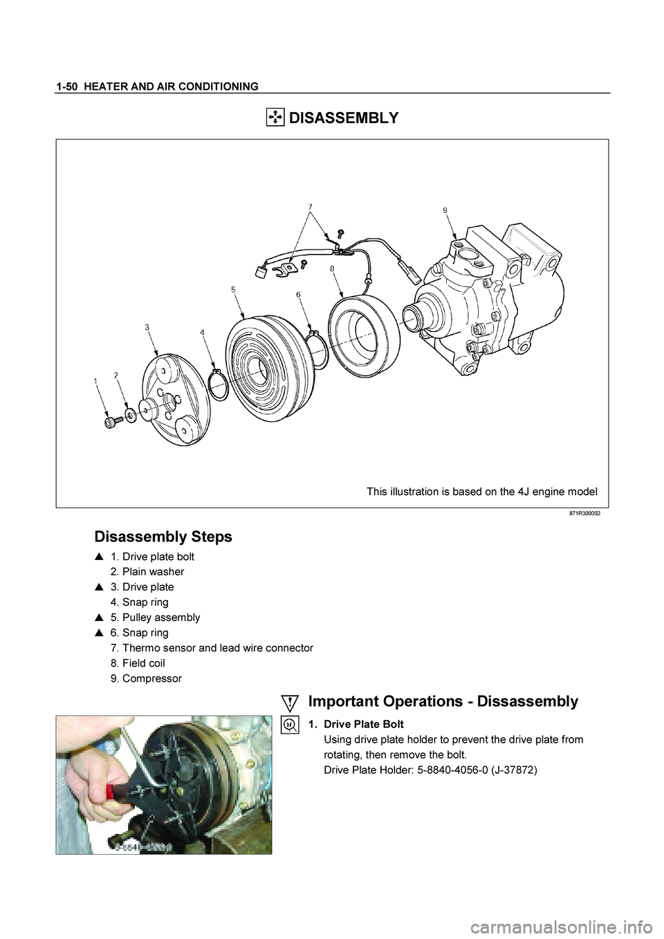
DISASSEMBLY
This illustration is based on the 4J engine model
871R300002
Disassembly Steps
� 1. Drive plate bolt
2. Plain washer
� 3. Drive plate
4. Snap ring
� 5. Pulley assembly
� 6. Snap ring
7. Thermo sensor and lead wire connector
8. Field coil
9. Compressor
Important Operations - Dissassembly
1. Drive Plate Bolt
Using drive plate holder to prevent the drive plate from rotating, then remove the bolt.
Drive Plate Holder: 5-8840-4056-0 (J-37872)
Page 3062 of 4264
1-52 HEATER AND AIR CONDITIONING
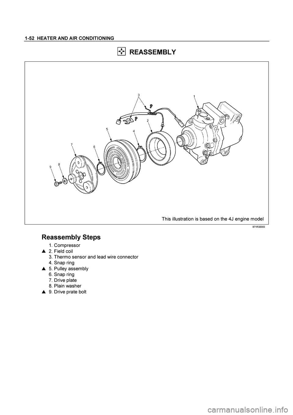
REASSEMBLY
This illustration is based on the 4J engine model
871R30003
Reassembly Steps
1. Compressor
� 2. Field coil
3. Thermo sensor and lead wire connector
4. Snap ring
� 5. Pulley assembly
6. Snap ring
7. Drive plate
8. Plain washer
� 9. Drive prate bolt
Page 3125 of 4264

MSG MODEL 7B-7
REMOVAL AND INSTALLATION
Read this Section carefully before performing any removal and installation procedure. This Section gives you
important points as well as the order of operation. Be sure that you understand everything in this Section before
you begin.
Important Operations - Removal
Battery Cable
Disconnect the negative (-) cable from the battery terminal.
Engine Hood
Apply setting marks to the engine hood and the engine hood
hinges before removing the engine hood.
Gear Shift Lever
1. Place the gear shift lever in the neutral position.
2. Remove the gear shift lever knob.
3. Remove the front console assembly.
4. Remove the gear shift lever grommet and dust cover.
5. Remove the gear shift lever cover bolts.
6. Remove the gear shift lever.
Note:
Cover the shift lever hole to prevent the entry of foreign
material into the transmission.
Lifting the Vehicle
1. Jack up the vehicle.
2. Place chassis stands at the front and the rear of the
vehicle.
Transmission Oil Draining
1. Remove the transmission oil drain plug.
2. Replace the drain plug after draining the oil.