2004 ISUZU TF SERIES brake
[x] Cancel search: brakePage 3987 of 4264
CONSTRUCTION AND FUNCTION 7A1-41
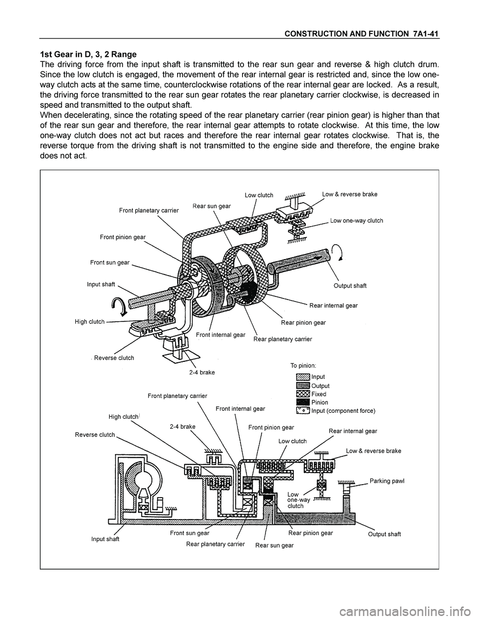
1st Gear in D, 3, 2 Range
The driving force from the input shaft is transmitted to the rear sun gear and reverse & high clutch drum.
Since the low clutch is engaged, the movement of the rear internal gear is restricted and, since the low one-
way clutch acts at the same time, counterclockwise rotations of the rear internal gear are locked. As a result,
the driving force transmitted to the rear sun gear rotates the rear planetary carrier clockwise, is decreased in
speed and transmitted to the output shaft.
When decelerating, since the rotating speed of the rear planetary carrier (rear pinion gear) is higher than that
of the rear sun gear and therefore, the rear internal gear attempts to rotate clockwise. At this time, the low
one-way clutch does not act but races and therefore the rear internal gear rotates clockwise. That is, the
reverse torque from the driving shaft is not transmitted to the engine side and therefore, the engine brake
does not act.
Page 3988 of 4264
7A1-42 CONSTRUCTION AND FUNCTION
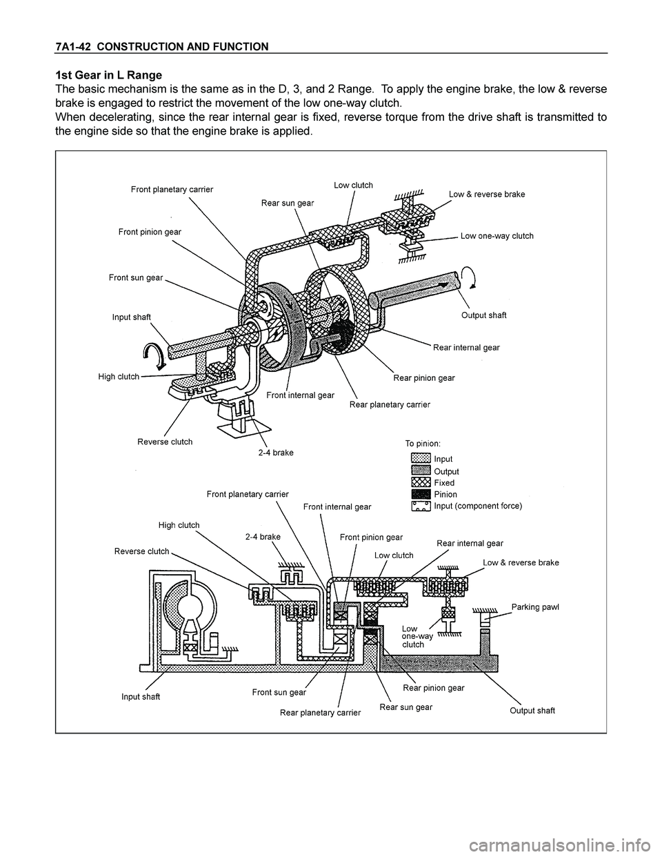
1st Gear in L Range
The basic mechanism is the same as in the D, 3, and 2 Range. To apply the engine brake, the low & reverse
brake is engaged to restrict the movement of the low one-way clutch.
When decelerating, since the rear internal gear is fixed, reverse torque from the drive shaft is transmitted to
the engine side so that the engine brake is applied.
Page 3989 of 4264
CONSTRUCTION AND FUNCTION 7A1-43
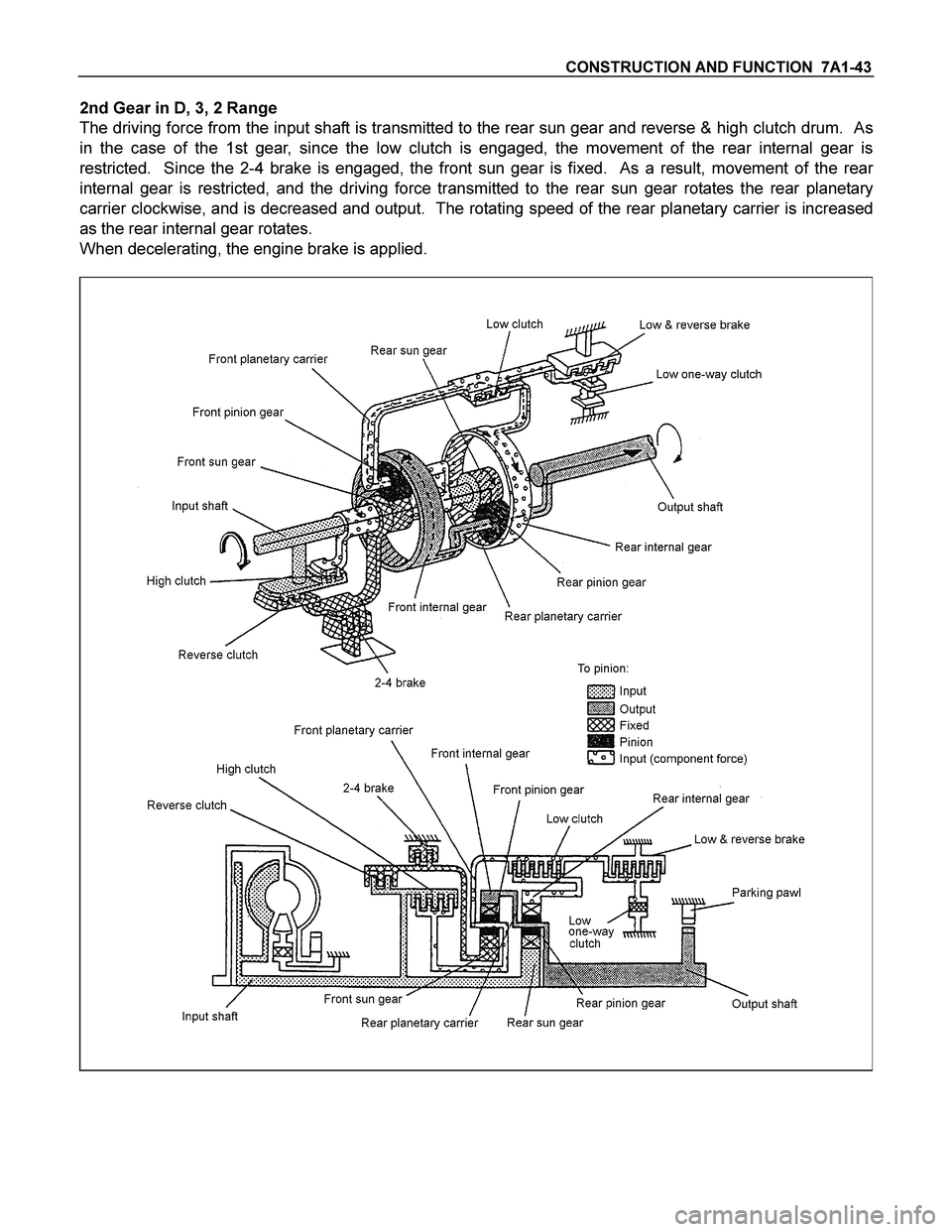
2nd Gear in D, 3, 2 Range
The driving force from the input shaft is transmitted to the rear sun gear and reverse & high clutch drum. As
in the case of the 1st gear, since the low clutch is engaged, the movement of the rear internal gear is
restricted. Since the 2-4 brake is engaged, the front sun gear is fixed. As a result, movement of the rear
internal gear is restricted, and the driving force transmitted to the rear sun gear rotates the rear planetary
carrier clockwise, and is decreased and output. The rotating speed of the rear planetary carrier is increased
as the rear internal gear rotates.
When decelerating, the engine brake is applied.
Page 3990 of 4264
7A1-44 CONSTRUCTION AND FUNCTION
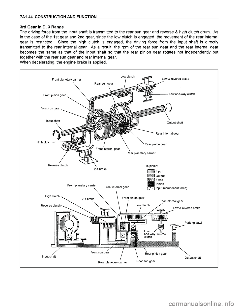
3rd Gear in D, 3 Range
The driving force from the input shaft is transmitted to the rear sun gear and reverse & high clutch drum. As
in the case of the 1st gear and 2nd gear, since the low clutch is engaged, the movement of the rear internal
gear is restricted. Since the high clutch is engaged, the driving force from the input shaft is directly
transmitted to the rear internal gear. As a result, the rpm of the rear sun gear and the rear internal gear
becomes the same as that of the input shaft so that the rear pinion gear rotates not independently but
together with the rear sun gear and rear internal gear.
When decelerating, the engine brake is applied.
Page 3991 of 4264
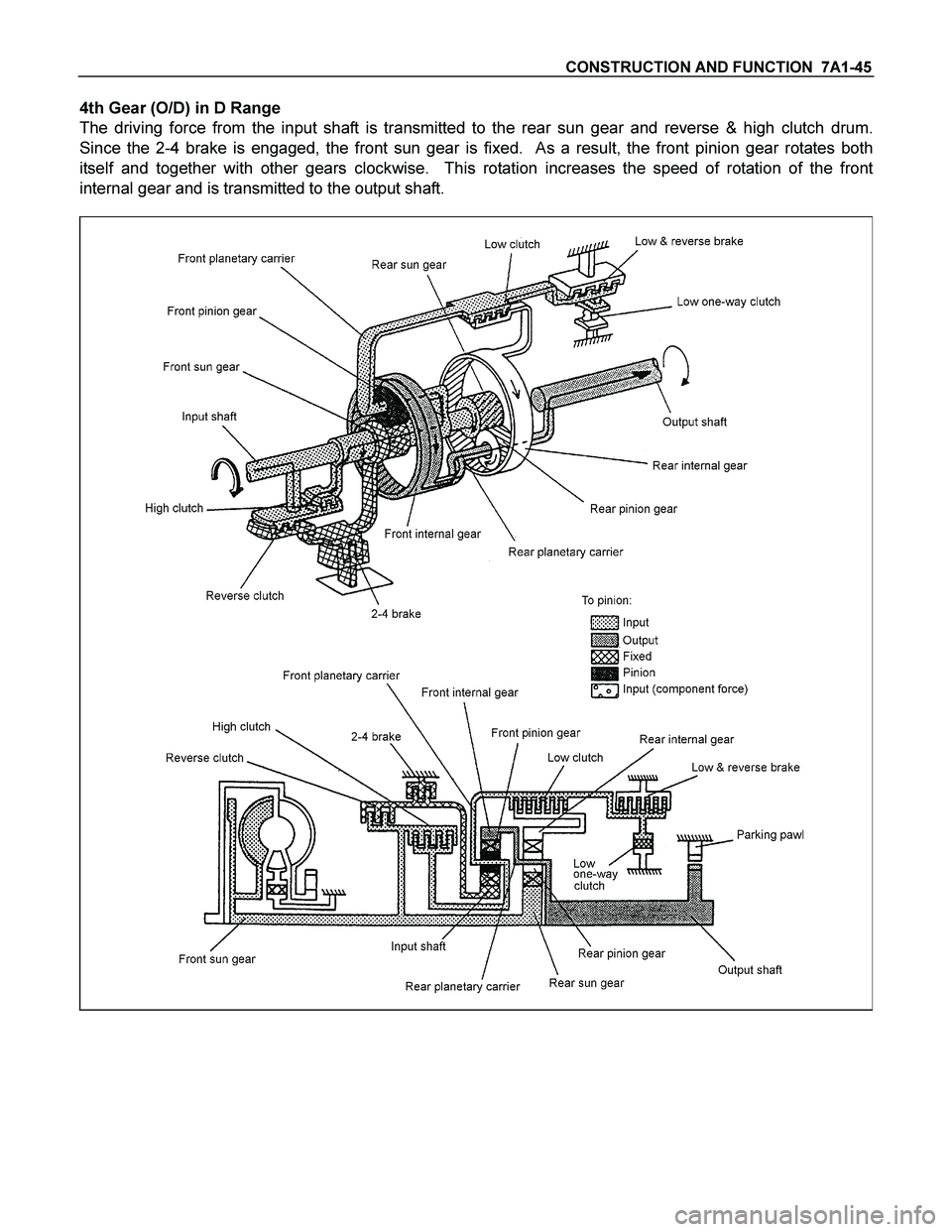
CONSTRUCTION AND FUNCTION 7A1-45
4th Gear (O/D) in D Range
The driving force from the input shaft is transmitted to the rear sun gear and reverse & high clutch drum.
Since the 2-4 brake is engaged, the front sun gear is fixed. As a result, the front pinion gear rotates both
itself and together with other gears clockwise. This rotation increases the speed of rotation of the front
internal gear and is transmitted to the output shaft.
Page 3993 of 4264
DIAGNOSIS (JR405E) 7A2-1
SECTION 7A2
DIAGNOSIS
TABLE OF CONTENTS
PAGE
BASIC TROUBLE SHOOTING..................................................................................................7A2-6
CHECK TRANS INDICATOR & SELF DIAGNOSIS..............................................................7A2-7
DIAGNOSIS WITH TECH 2........................................................................................................7A2-9
TECH 2 CONNECTION .................................................................................................. 7A2-9
TECH 2 OPERATING FLOW CHART (START UP)..............................................................7A2-10
TYPICAL SCAN DATA................................................................................................................7A2-13
MISCELLANEOUS TEST...........................................................................................................7A2-14
INTERMITTENT DIAGNOSIS....................................................................................................7A2-16
SNAPSHOT DISPLAY WITH TIS 2000....................................................................................7A2-17
SERVICE PROGRAMMING SYSTEM (SPS) ................................................................. 7A2-21
CIRCUIT DIAGRAM.....................................................................................................................7A2-24
PART LOCATION........................................................................................................................7A2-26
CONNECTOR LIST.....................................................................................................................7A2-31
DIAGNOSIS TROUBLE CODE TABLE...................................................................................7A2-33
FAIL-SAFE FUNCTION..............................................................................................................7A2-35
DTC P0722 (FLASH CODE 11) VEHICLE SPEED SENSOR NO SIGNAL......................7A2-36
DTC P0727 (FLASH CODE 13) ENGINE REVOLUTION SENSOR NO SIGNAL............7A2-38
DTC P0717 (FLASH CODE 14) TURBINE SPEED SENSOR NO SIGNAL......................7A2-40
DTC P0710 (FLASH CODE 15) ATF TEMPERATURE SENSOR FAILURE....................7A2-42
DTC P0560 (FLASH CODE 16) SYSTEM VOLTAGE FAILURE........................................7A2-43
DTC P0705 (FLASH CODE 17) INHIBITOR SWITCH FAILURE........................................7A2-44
DTC P1120 (FLASH CODE 22) THROTTLE SIGNAL FAILURE........................................7A2-46
DTC P1875 (FLASH CODE 25) GND RETURN CIRCUIT FAILURE.................................7A2-47
DTC P0753 (FLASH CODE 31) LOW & REVERSE BRAKE DUTY
SOLENOID FAILURE................................................................................................................7A2-48
DTC P0758 (FLASH CODE 32) 2-4 BRAKE DUTY SOLENOID FAILURE......................7A2-51
DTC P0763 (FLASH CODE 33) HIGH CLUTCH DUTY SOLENOID FAILURE................7A2-54
DTC P0768 (FLASH CODE 34) LOW CLUTCH DUTY SOLENOID FAILURE................7A2-57
Page 3994 of 4264
7A2-2 DIAGNOSIS (JR405E)
PAGE
DTC P0748 (FLASH CODE 35) LINE PRESSURE SOLENOID FAILURE.......................7A2-60
DTC P1860 (FLASH CODE 36) LOCK-UP DUTY SOLENOID FAILURE.........................7A2-62
DTC P1853 (FLASH CODE 26) LOW & REVERSE BRAKE PRESSURE
SWITCH FAILURE......................................................................................................................7A2-64
DTC P1858 (FLASH CODE 27) 2-4 BRAKE PRESSURE SWITCH FAILURE................7A2-68
DTC P1863 (FLASH CODE 28) HIGH CLUTCH PRESSURE SWITCH FAILURE..........7A2-72
DTC P0731 (FLASH CODE 41) 1st GEAR RATIO ERROR................................................7A2-76
DTC P0732 (FLASH CODE 42) 2nd GEAR RATIO ERROR...............................................7A2-76
DTC P0733 (FLASH CODE 43) 3rd GEAR RATIO ERROR................................................7A2-76
DTC P0734 (FLASH CODE 44) 4th GEAR RATIO ERROR................................................7A2-76
DTC P1750 (FLASH CODE 51) LOW & REVERSE BRAKE FAIL-SAFE
VALVE FAILURE........................................................................................................................7A2-78
DTC P1755 (FLASH CODE 52) 2-4 BRAKE FAIL-SAFE VALVE FAILURE....................7A2-80
DTC P0602 Programming Error ................................................................................... 7A2-82
SYMPTOM DIAGNOSIS.............................................................................................................7A2-83
SYMPTOM DIAGNOSIS TABLE...............................................................................................7A2-84
No. A1: VEHICLE DOES NOT RUN IN D, 3, 2, L and RANGE..........................................7A2-93
No. A2: VEHICLE DOES NOT RUN IN R RANGE................................................................7A2-94
No. A3: VEHICLE DOES NOT RUN IN D, 3, 2 and RANGE...............................................7A2-95
No. B1: VEHICLE RUNS IN N RANGE...................................................................................7A2-96
No. B2: POOR ACCELERATION AT STARTING.................................................................7A2-97
No. B3: ENGINE RACE UP DURING STARTING (SLIP)....................................................7A2-100
No. B4: LARGE SHOCK WHEN SHIFT LEVER IS CHANGED TO N TO D
RANGE OR N TO R RANGE....................................................................................................7A2-103
No. B5: ENGINE STALLS WHEN SELECTING FROM N RANGE TO R, D, 3, 2
OR L RANGE...............................................................................................................................7A2-104
No. B6: ENGINE STARTER DOES NOT RUN IN P OR N RANGE...................................7A2-106
No. B7: ENGINE STARTER RUNS EXCEPT IN P OR N RANGE.....................................7A2-106
No. B8: EXTENDED TIME LAG WHEN SHIFT LEVER IS CHANGED TO N TO D........7A2-106
No. B9: EXTENDED TIME LAG WHEN SHIFT LEVER IS CHANGED TO N TO R........7A2-106
No. B10: BRAKE IS APPLIED IN R RANGE..........................................................................7A2-107
No. B11: INSUFFICIENT STARTING OR SHAKING IN D RANGE...................................7A2-107
Page 3996 of 4264
7A2-4 DIAGNOSIS (JR405E)
PAGE
NO. D3: GEAR SHIFT POINT IS LOW OR HIGH AT ALL POINT................................. 7A2-120
NO. D4: GEAR SHIFT POINT IS LOW OR HIGH AT LIMITED POINT ......................... 7A2-120
NO. D5: NO KICK-DOWN .............................................................................................. 7A2-120
NO. E1: NO GEAR SHIFT .............................................................................................. 7A2-121
NO. E2: ONLY 4TH GEAR (O/D) IS NOT SELECTABLE ............................................. 7A2-124
NO. E3: GEAR IS SHIFTED 2ND TO 3RD IN 2 RANGE ............................................... 7A2-126
NO. E4: GEAR IS SHIFTED 1ST TO 2ND IN L RANGE................................................ 7A2-126
NO. E5: GEAR IS SHIFTED 3RD TO 4TH IN 3 RANGE................................................ 7A2-126
NO. F1: LOW MAXIMUM SPEED OR POOR ACCELERATION ................................... 7A2-127
NO. F2: ENGINE RACES UP DURING ACCELERATION (SLIP) ................................. 7A2-130
NO. F3: NOISE OR VIBRATION DURING THE RUNNING IN R, D, 3, 2 OR L
RANGE .......................................................................................................................... 7A2-130
NO. F4: ENGINE BRAKE DOES NOT APPLY IN L RANGE......................................... 7A2-130
NO. F5: ENGINE STALLS BEFORE VEHICLE STOPS FROM RUNNING ................... 7A2-131
NO. G1: VEHICLE MOVES IN P RANGE OR PARKING GEAR IS NOT
DISENGAGED OTHER THAN P RANGE ..................................................................... 7A2-131
NO. G2: CREEP FORCE IS LARGE.............................................................................. 7A2-131
NO. G3: CREEP FORCE IS SMALL .............................................................................. 7A2-132
NO. G4: LARGE NOISE DURING IDLING WITH THE VEHICLE IN STOP STATE ...... 7A2-133
NO. H1: JUDDER OCCURS AT THE LOCK-UP ........................................................... 7A2-133
NO. H2: LARGE LOCK-UP SHOCK .............................................................................. 7A2-133
NO. H3: LOCK-UP POINT IS HIGH OR LOW ............................................................... 7A2-133
NO. I1: NO LOCK-UP .................................................................................................... 7A2-134
NO. J1: OIL LEAKS FROM BREATHER ....................................................................... 7A2-136
NO. J2: OIL LEAKS BETWEEN ENGINE AND CONVERTER HOUSING .................... 7A2-136
NO. J3: OIL LEAKS BETWEEN MAIN CASE AND CONVERTER HOUSING.............. 7A2-136
NO. J4: OIL LEAKS BETWEEN MAIN CASE AND REAR HOUSING .......................... 7A2-136
NO. J5: OIL LEAKS FROM OIL PAN ............................................................................ 7A2-136
NO. J6: OIL LEAKS FROM MANUAL SHAFT OIL SEAL ............................................. 7A2-136
NO. J7: OIL LEAKS FROM OIL COOLER PIPE JOINT................................................ 7A2-136
NO. Z1: TRANSMISSION OVERHEAT .......................................................................... 7A2-136
NO. Z2: MODE LAMP (POWER DRIVE OR 3RD START) DOES NOT LIGHT UP
WHEN THE POWER MODE OR 3RD START MODE IS TURNED ON........................ 7A2-137