Page 3486 of 4264
3B-56 POWER-ASSISTED STEERING SYSTEM
CAUTION: The wheel of the vehicle must be straight
ahead and the steering column in the "LOCK"
position before disconnecting the steering column
from the steering gear. Failure to do so will cause
the SRS coil assembly to become uncentered which
will cause damage to the SRS coil assembly. (with
SRS air bag)
5. Remove the engine hood opening lever and
steering lower cover.
6. Remove the driver knee bolster (reinforcement).
7. Disable the SRS (Refer to "Disabling the SRS" in
this section). (with SRS air bag)
8. Check the both side hole of the steering cover. (with
SRS air bag)
060R300025
9. Check the position of the pins in a hole. Push the
pin in the direction of an arrow. (with SRS air bag)
060R300032
10. Push the four pins at �
5�
6 mm bar. (with SRS ai
r
bag)
060R300031
11. Cancel the lock four pins. (with SRS air bag)
12. Loosen the horn pad fixing screw at the rear of the
steering wheel (without SRS air bag).
430R300009
Page 3487 of 4264
POWER-ASSISTED STEERING SYSTEM 3B-57
13. Disconnect the SRS air bag connector and horn
lead connector located behind the air bag assembl
y
and remove the air bag assembly. (with SRS air
bag)
060R300041
14. Remove the horn pad and the horn leads at the
center of the wheel (without SRS air bag).
NOTE: It removes previously from the spoke bottom.
RTW33BSH000401
15.
Apply a setting mark (1) across the steering wheel
and shaft so parts can be reassembled in thei
r
original position. Move the front wheels to the
straight ahead position, then use steering wheel
remover 5-8521-0016-0 to remove the steering
wheel.
430R300008
430RX005-X
Page 3489 of 4264
.
431RW031
Column Universal Joint (between the
power steering unit and the steeri")
POWER-ASSISTED STEERING SYSTEM 3B-59
Check clearance between capsule and bracket. If must
be within 1mm (0.039 in).
431RW031
Column Universal Joint (between the
power steering unit and the steering shaft)
If the resistance is felt when checked by rotate the joint,
replace the lower second steering shaft.
Shaft Universal Joint (between the lower
second steering shaft and the second
steering shaft)
If the resistance is felt when checked by rotate the joint,
replace the second steering shaft assembly.
Tilt Mechanism
Tilt mechanism should moves smoothly.
While locked the tilt mechanism, be sure the steering
column latch securely by pushing the steering wheel
upward and downward.
Installation
1. Align the setting marks on the second steering shaft
and the steering column assembly (applied at
disassembly).
2. Connect the steering column assembly to the second
steering shaft. Tighten the bolts to the specified
torque.
Torque: 26 - 36 N�
�� �m (2.7 – 3.7 kg�
�� �m/20 - 27 lb ft)
3. Thread the steering column assembly through the
hole in the dashpanel. Temporarily tighten the
steering column and the second steering shaft fixing
bolt.
4. Connect the lower second steering shaft and the
second steering shaft. Tighten the universal joint
bolts to the specified torque.
Torque: 26 - 36 N�
�� �m (2.7 – 3.7 kg�
�� �m/20 - 27 lb ft)
5. Tighten the steering column fixing bolt (pedal brkt
side) to the specified torque (This bolt was
temporarily tighten in Step 3).
Torque: 18 -23 N�
�� �m (1.8 – 2.3 kg�
�� �m/13 - 17 lb ft)
6. Tighten the second steering shaft fixing bolt to the
specified torque (This bolt was temporarily tightened
in Step 3)
Torque: 18 -23 N�
�� �m (1.8 – 2.3 kg�
�� �m/13 - 17 lb ft)
7. Tighten the steering column fixing bolt (dashpanel
side) to the specified torque (This bolt was
temporarily tighten in Step 3).
Torque: 18 -23 N�
�� �m (1.8 – 2.3 kg�
�� �m/13 - 17 lb ft)
8. Install combination switch and SRS coil assembly.
After installation of combination switch assembly,
connect the combination switch wiring harness
connector and the SRS 2-way connector located
under the steering column.
Page 3490 of 4264

CAUTION: When turning the SRS coil counte
r")
3B-60 POWER-ASSISTED STEERING SYSTEM
9. Turn the SRS coil counter clockwise to full, return
about 3 turns and align the neutral mark. (with SRS
air bag)
CAUTION: When turning the SRS coil counte
r
clockwise to full, stop turning if resistance is felt.
Forced further turning may damage to the cable in
the SRS coil.
826RW014
10. When installing the steering column cover, be sure to
route each wire harness as illustrated so that the
harnesses do not catch any moving parts.
825RW017
Legend
(1) Steering Column Cover
(2) Starter Switch Harness
(3) Combination Switch Harness
(4) Inflator Module Harness
11. Install steering wheel and align the setting marks
made when removing.
Refer to the adjustment method in case a mark is
not attached in this section.
NOTE: Confirm SRS and Horn harness connector is
fixed by the steering wheel.
RTW33BSH000601
CAUTION: Never apply force to the steering wheel in
direction of the shaft by using a hammer or othe
r
impact tools in an attempt to remove the steering
wheel. The steering shaft is designed as an energy
absorbing unit.
12. Tighten the steering wheel fixing nut to the specified
torque.
Torque: 31 - 39 N�
�� �m (3.2 – 4.0 kg�
�� �m/23 - 29 lb ft)
13. Support the module and carefully connect the
module connector and horn lead, then install inflato
r
module.
NOTE: Pass the lead wire through the tabs on the
plastic cover (wire protector) of inflator to prevent lead
wire from being pinched.
14. Tighten bolts to specified torque.
Torque: 2 - 4 N�
�� �m (0.2 – 0.4 kg�
�� �m/17 - 35 lb in)
15. Install driver knee bolster (reinforcement).
16. Install instrument panel lower cover.
17. Install the engine hood opening lever.
18. Connect the yellow 2-way SRS connector and horn
lead located under the steering column.
19. Connect the battery "-" terminal cable. (with SRS ai
r
bag)
Page 3492 of 4264
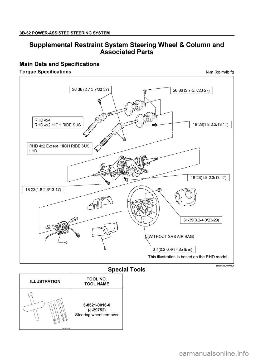
3B-62 POWER-ASSISTED STEERING SYSTEM
Supplemental Restraint System Steering Wheel & Column and
Associated Parts
Main Data and Specifications
Torque Specifications N�
m (kg�
m/lb ft)
This illustration is based on the RHD model.
RTW43BLF000301
Special Tools
ILLUSTRATION
TOOL NO.
TOOL NAME
5-8521-0016-0
(J-29752)
Steering wheel remover
Page 3499 of 4264
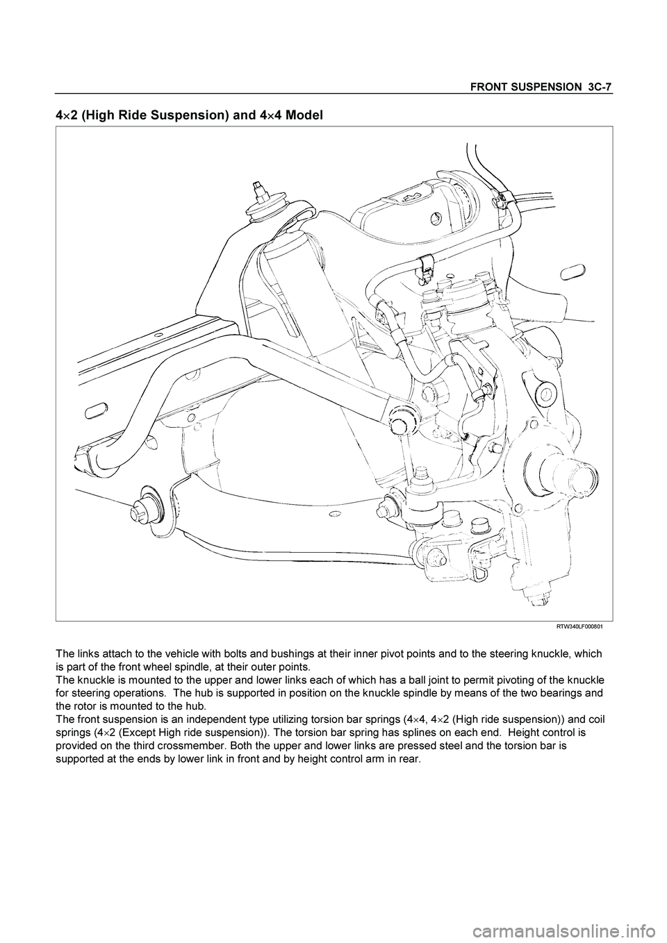
FRONT SUSPENSION 3C-7
4
�
�� �2 (High Ride Suspension) and 4
�
�� �4 Model
RTW340LF000801
The links attach to the vehicle with bolts and bushings at their inner pivot points and to the steering knuckle, which
is part of the front wheel spindle, at their outer points.
The knuckle is mounted to the upper and lower links each of which has a ball joint to permit pivoting of the knuckle
for steering operations. The hub is supported in position on the knuckle spindle by means of the two bearings and
the rotor is mounted to the hub.
The front suspension is an independent type utilizing torsion bar springs (4�
4, 4�
2 (High ride suspension)) and coil
springs (4�
2 (Except High ride suspension)). The torsion bar spring has splines on each end. Height control is
provided on the third crossmember. Both the upper and lower links are pressed steel and the torsion bar is
supported at the ends by lower link in front and by height control arm in rear.
Page 3501 of 4264
FRONT SUSPENSION 3C-9
Shock Absorber
Shock Absorber and Associated Parts
RTW440LF001201
Legend
(1)
Shock Absorber ASM with coil
(2)
Nut
(3)
Nut
(4)
Nut
(5)
Lower ball joint Nut and cot ter pin
(6)
Nut
(7)
Bolt
(8)
Cam bolt
Removal
1. Raise the vehicle and support it with suitable
safety stands.
2. Remove wheel and tire assembly. Refer to Wheel
Replacement in this section.
3. Remove nut (6).
CAUTION: Be careful not o break the ball joint boot.
Page 3503 of 4264
, then tighten it to the specified
torque.
Torque: 55N
�
�� �m (5.6kg
�
�� �m/41lb ft)
3.")
FRONT SUSPENSION 3C-11
NOTE: Paint mark to be outer side of after assembly to
vehicle.
2. Install nut (2), then tighten it to the specified
torque.
Torque: 55N
�
�� �m (5.6kg
�
�� �m/41lb ft)
3. Install bolt (7) and nut (4), then tighten to the
specified torque.
Buffer clearance: 25.9 mm (1.02 in)
Torque: 137N�
�� �m (14.0kg�
�� �m/101 lb ft)
NOTE: Apply oil to the thread.
NOTE: Tighten the bolt and nut with the parts in the
position shown in the illustration below.
RTW340SH001301-X
4. Install nut (6), then tighten it to the specified
torque.
Torque: 50N�
�� �m (5.1kg�
�� �m/37 lb ft)
5. Tighten the cam bolt (8) and nut (3), it to the
interim torque, then turn the cam bolt to the setting
mark applied during disassembly.
6. Install ball joint nut, then tighten it to the specified
torque with just enough additional torque to align
cotter pin holes. Install new cotter pin (5).
Torque: 147N�
�� �m (15.0kg�
�� �m/108 lb ft)
NOTE: Check the trim height. Refer to Front Alignment
Inspection and Adjustment.
7. Nut (3) tighten it to the specified torque.
Buffer clearance: 25.9 mm (1.02 in)
Torque: 186N�
�� �m (19.0kg�
�� �m/137 lb ft)
NOTE: Apply oil to the thread.
NOTE: Tighten the bolt and nut with the parts in the
position shown in the illustration below.
RTW340SH001301-X
8. Install wheel and tire assembly. Refer to wheel in
this section.


060R30")

Shock Absorber ASM with coil
(2)
Nut
(3)
Nut
(4)
Nut
(5)
Lower b")