Page 172 of 4264
4B-8 REAR AXLE
SERVICING
Rear Axle Oil Replacement
Oil Capacity liters (US/UK gal.)
2.4 (0.63/0.53)
Specified gear oil GL5 (API grade)(STD)
GL5LSD (LSD)
Filler Plug and Drain Plug Torque N�m (kgf�m/lb�ft)
78 (8.0/58)
Axle Shaft Roller Bearing Endplay
Inspection
1.
Raise and suitably support vehicle.
2.
Remove the wheel and brake drum.
3.
Inspect the axle shaft roller bearing endplay using
dial gauge.
Endplay mm (in
)
Standard 0 �
0.2 (0 �
0.008)
If the endplay exceeds 0.2mm (0.008 in), replace the
axle shaft roller bearings.
Refer to Rear Axle Reassembly.
RTW34BSH000101
Page 173 of 4264
REAR AXLE 4B-9
REAR AXLE
1.
Refer to Section 3E "WHEEL and TIRE" for road
wheel Disassembly procedure.
2.
Refer to Section 5 "BRAKE" for rear brake
removal procedure.
RTW34BLF000401
Legend
1. Brake Drum
2. Bolt and Nut
3. Axle Shaft Assembly with Brake
4.
Shim
5. Snap Ring
6. Axle Shaft
7. Sensor Rotor (with ABS)
Spacer (without ABS)
8.
Double Taper Roller Bearing
9. Oil Seal
10.
Bearing Holder
11. Rear Brake
12. Bolt and Nut
13. Differential Assembly
14. Rear Axle Case Assembly
15. Wheel Pin
16. Axle Case Oil Seal
17.
Front
Page 174 of 4264
4B-10 REAR AXLE
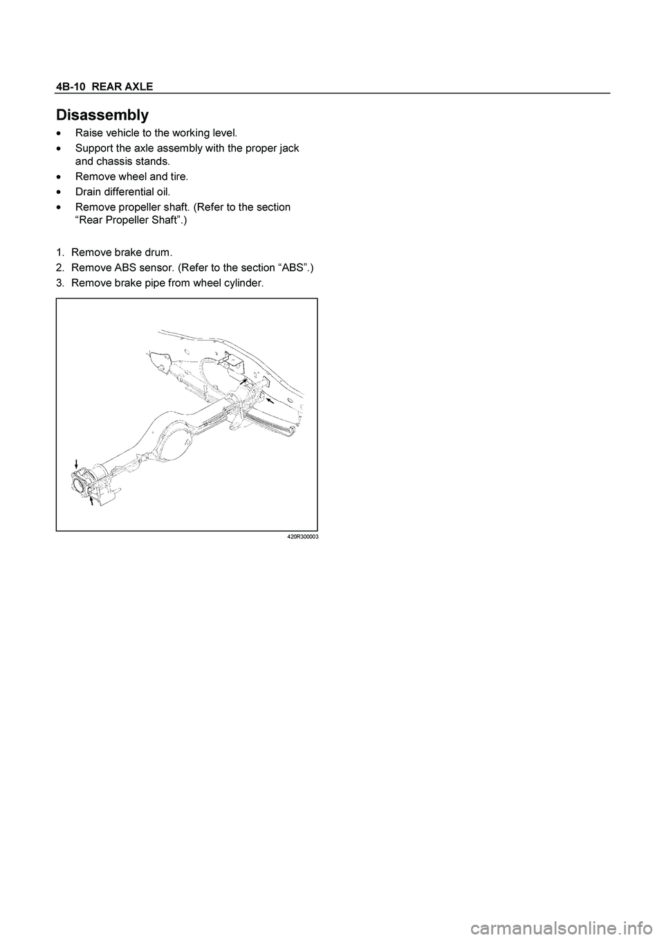
Disassembly
�
Raise vehicle to the working level.
�
Support the axle assembly with the proper jack
and chassis stands.
�
Remove wheel and tire.
�
Drain differential oil.
�
Remove propeller shaft. (Refer to the section
“Rear Propeller Shaft”.)
1.
Remove brake drum.
2. Remove ABS sensor. (Refer to the section “ABS”.)
3. Remove brake pipe from wheel cylinder.
420R300003
Page 175 of 4264
REAR AXLE 4B-11
305R30000
Legend
1.
Tension Pin
2.
Shoe Clamp Spring
3.
Return Spring
4.
Shoe Assembly with Parking Brake Lever
5.
Shoe Assembly with Adjuster Lever
6.
Spring
7.
Parking Brake Cable
8.
Adjuster
9.
Parking Brake Lever
10.
Adjuster Spring
11.
Adjuster Lever
12.
Wheel Cylinder
13.
Back plate
4.
Remove tension pin and shoe clamp spring.
5.
Remove return spring.
6.
Remove shoe assembly with parking brake lever.
7. Remove shoe assembly with adjuster lever and
spring.
8.
Remove parking brake inner cable from parking
brake lever.
9.
Use offset box wrench to compress locking lugs
on the cable, then remove parking brake outer
cable from back plate.
311RS012
Page 176 of 4264

4B-12 REAR AXLE
Legend
1.
Offset Box Wrench
10.
Remove wheel cylinder.
11.
Remove bearing holder fixing nuts.
12.
Take out axle shaft assembly with back plate and
set it on a bench press as following illustration.
Put bolt head on thick steel plate.
When axle shaft is extracted, since axle case oil
seal is damaged, axle case oil seal.
13.
Remove snap ring. Use snap ring pliers to
remove. Snap ring is prohibition of reuse.
14.
Remove shim (If so equipped)
15.
Remove sensor rotor (or spacer), double tape
r
roller bearing, oil seal, bearing holder, and back
plate from axle shaft by means of a press.
�
Discard used oil seal, double taper roller
bearing, snap ring, ABS sensor rotor and
spacer.
A03R300002
Legend
1.
Bench Press Fitting
2. Steel Plate (25-30 mm thickness)
3. Axle Shaft
16. Remove differential assembly fixing bolts and
nuts and take out differential assembly.
17.
Remove wheel pin from axle shaft, using the
remover 5-8840-0079-0.
420L100009
18.
Remove axle case oil seal.
�
Discard used oil seal.
Page 178 of 4264
4B-14 REAR AXLE
Reassembly
1.
Using the oil seal installer 5-8840-2202-0, install
new axle case oil seal.
420R300004
Note :
Confirm that the dimention : A should be 34.5 –
36.1 mm (1.36 – 1.42 in)
A03R300004
2.
Install new oil seal in bearing holder, using the oil
seal installer 9-8522-1269-0.
F04R300002
Legend
1.
Oil Seal
2.
Bearing Holder
3.
Drive wheel pin into axle shaft flange, using a
hammer.
4.
Differential assembly
a.
Clean the mating surface of axle case and
differential carrier.
b.
Apply Three Bond 1215 (TB1215) or
equivalent on the surface of differential
assembly as flowing illustration.
425RS006
c. Tighten bolts and nuts to the specified torque.
Torque : Bolt
64 N�
m (6.5 kg�
m/47 lb�
ft)
Nut
44 N�
m (4.5 kg�
m/33 lb�
ft)
Page 180 of 4264

4B-16 REAR AXLE
8.
Certainly install new snap ring, use snap ring pliers.
When transform or damage, replace new one.
RTW34BMH000101
Legend
1.
Snap ring
2.
Crevice
3.
Sensor rotor (with ABS)
Spacer (without ABS)
9.
Insert a shim of sufficient thickness between snap
ring and end of sensor rotor (or spacer).
Standard
0 �
0.2 mm (0 �
0.008 in)
Crevice is measured using thickness gauge, and
when crevice exceeds 0.2 (mm), it adjusts so that
is may become 0.2 (mm) or less using shim.
Shim Pats No.
Thickness
1 9-41519110-�
0.18 mm (0.0071 in)
2 8-97130387-�
0.50 mm (0.0197 in)
Crevice
No. of shim
Total
Mm (in)
1 2
mm (in)
1.0(0.0394) �
2
1.00(0.0394)
0.9(0.0354)
2
1
0.86(0.0339)
0.8(0.0315)
1
1
0.68(0.0268)
0.7(0.0276)
1
1
0.68(0.0268)
0.6(0.0236)
�
1
0.50(0.0197)
0.5(0.0197)
�
1
0.50(0.0197)
0.4(0.0158)
2 �
0.36(0.0142)
0.3(0.0118)
1 �
0.18(0.0071)
0.2(0.0079)
1 �
0.18(0.0071)
10. Install axle shaft assembly in rear axle case
assembly.
Note:
When inserting an axle shaft, it inserts so that an
oil seal may not be damaged.
11. Install and tighten bearing holder fixing nut to the
specified torque.
Torque : 84 N�
m (8.6 kg�
m/62 lb�
ft)
12. Install wheel cylinder and tighten the bolt to the
specified torque.
Torque : 9 N�
m (0.9 kg�
m/78 lb�
ft)
13. Install parking brake outer cable in back plate and
inner cable in parking brake lever.
Page 181 of 4264
REAR AXLE 4B-17
14.
Install shoe assembly with adjuster lever, shoe
assembly with parking brake lever and spring.
15.
Install return spring.
16.
Install shoe clamp spring and tension pin.
305R300001
Legend
1.
Tension Pin
2.
Shoe Clamp Spring
3.
Return Spring
4.
Shoe Assembly with Parking Brake Lever
5.
Shoe Assembly with Adjuster Lever
6.
Spring
7.
Parking Brake Cable
8.
Adjuster
9.
Parking Brake Lever
10.
Adjuster Spring
11.
Adjuster Lever
12.
Wheel Cylinder
13.
Back plate

2.4 (0.63/0.53)
Specified gear oil GL5 (API grade)(STD)
GL5LSD (LSD)
Filler Plug and Drain Plug Torque")