Page 63 of 4264
SUPPLEMENTAL RESTRAINT SYSTEM 9A-43
NOTE: Confirm SRS and Horn harness connector is
fixed by the steering wheel.
RTW33BSH000601
14.Tighten the steering wheel fixing nut to the
specified torque.
Torque: 35 N�
�� �m (3.5 kg�
�� �m/25 lb ft)
15. Install the SRS air bag assembly. (Refer to “Drive
r
Air Bag Assembly in this section)
Page 64 of 4264

9A-44 SUPPLEMENTAL RESTRAINT SYSTEM
Passenger Air Bag Assembly
Service Precautions
WARNING: SAFETY PRECAUTIONS MUST BE
FOLLOWED WHEN HANDLING A DEPLOYED AI
R
BAG ASSEMBLY. AFTER DEPLOYMENT, THE AIR
BAG ASSEMBLY SURFACE MAY CONTAIN A
SMALL AMOUNT OF SODIUM HYDROXIDE, A BY–
PRODUCT OF THE DEPLOYMENT REACTION,
THAT IS IRRITATING TO THE SKIN AND EYES.
MOST OF THE POWER ON THE AIR BAG
ASSEMBLY IS HARMLESS. AS A PRECAUTION,
WEAR GLOVES AND SAFETY GLASSES WHEN
HANDLING A DEPLOYED AIR BAG ASSEMBLY,
AND WASH YOUR HANDS WITH MILD SOAP AND
WATER AFTERWARDS.
WARNING: WHEN CARRYING A LIVE AIR BAG
ASSEMBLY, MAKE SURE THE BAG AND TRIM
COVER ARE POINTED AWAY FROM YOU. NEVE
R
CARRY AIR BAG ASSEMBLY BY THE WIRES OR
CONNECTOR ON THE UNDERSIDE OF MODULE.
IN THE CASE OF AN ACCIDENTAL DEPLOYMENT,
THE BAG WILL THEN DEPLOY WITH MINIMAL
CHANCE OF INJURY. WHEN PLACING ALIVE AI
R
BAG ASSEMBLY ON A BENCH OR OTHER
SURFACE, ALWAYS FACE BAG AND RIM COVER
UP, AWAY FROM THE SURFACE. NEVER REST A
STEERING COLUMN ASSEMBLY ON THE
STEERING WHEEL WITH THE AIR BAG
ASSEMBLY FACE DOWN AND COLUMN
VERTICAL. THIS IS NECESSARY SO THAT A FREE
SPACE IS PROVIDED TO ALLOW THE AIR BAG
ASSEMBLY TO EXPAND IN THE UNLIKELY EVENT
OF ACCIDENTAL DEPLOYMENT. OTHERWISE,
PERSONAL INJURY COULD RESULT.
WARNING: IN THE EVENT DEPLOYMENT HAS
OCCURRED, INSPECT COIL ASSEMBLY WIRE
FOR ANY SIGNS OF SCORCHING, MELTING O
R
ANY OTHER DAMAGE DUE TO EXCESSIVE HEAT.
IF THE COIL HAS BEEN DAMAGED, REPLACE IT.
Removal
1. Disable the SRS. (Refer to “Disabling the SRS”in
this section)
2. Remove glove box.
3. Remove glove box cover.
4. Remove passenger air bag assembly fixing bolts
and nuts. Universal joint is used when removing a
nut.
060R300043
060R300044
5. Remove passenger air bag assembly.
6. Disconnect passenger air bag assembly harness
connector.
Page 67 of 4264
SUPPLEMENTAL RESTRAINT SYSTEM 9A-47
Main Data and Specifications
Fastener Tightening Specification
Application N�
�� �m kg�
�� �m Ft.lb
SRS control unit 7 0.7 5
Steering wheel fixing bolt 35 3.5 25
Steering column (dash panel side fixing bolts) 20 2.0 14
Steering column (Pedal bracket fixing bolt) 20 2.0 14
Steering column (Universal joint fixing bolt) 31 3.2 23
Passenger Air Bag fixing bolt & nut 8 0.8 5.8
Pretensioner seat belt bolt 55 5.6 40
Page 70 of 4264
9A-50 SUPPLEMENTAL RESTRAINT SYSTEM
5-8840-2795-0 SRS Adapter for
Deployment Tool
901RW107
The 5-8840-2795-0 SRS Adapter for Deployment Tool
must be used with 5-8840-2468-0 SRS Deployment
Tool.
5-8521-0016-0 Steering Wheel remover
LNW28BSH003101
Page 139 of 4264

4�
2 Model
Engine Model 4JA1-T(L) 4JA1-TC 4JH1-TC
Transmission Type 5 M/T (MUA) 5M/T (MUA) 4A/T
Wheel Base")
PROPELLER SHAFT 4A-3
MAIN DATA AND SPECIFICATIONS
REAR PROPELLER SHAFT
mm(in)
4�
2 Model
Engine Model 4JA1-T(L) 4JA1-TC 4JH1-TC
Transmission Type 5 M/T (MUA) 5M/T (MUA) 4A/T
Wheel Base Long Long Extra Long Long
Front Suspension � High Ride
SuspensionExcept High
Ride
Suspension� �
Rear Axle �
220mm �
�
�
Type �
OBS �
�
�
Outside Diameter mm 75 68.9 68.9 68.9 63.5
(in) (2.95) (2.71) (2.71) (2.71) (2.50)
Inside Diameter mm 71.8 64.9 64.9 64.9 60.3
(in) (2.89) (2.63) (2.63) (2.63) (2.44)
Length 1st(L1) mm 799.5 798.5 801.5 946.5 720.5
(in) (31.48) (31.44) (31.56) (37.26) (28.37)
2nd(L2) mm 796 801 796 801 801
(in) (31.34) (31.54) (31.34) (31.54) (31.54)
Spline Major mm 29.89 29.89 29.89 29.89 29.89
Diameter (in) (1.18) (1.18) (1.18) (1.18) (1.18)
Fix Bolt Size M10 M10 M10 M10 M10
* OBS - Outboard Slip (Spline Engagement To T/M)
mm(in)
4�
2 Model
Engine Model C24SE
6VE1
Transmission Type 5M/T (MUA)
5M/T (MUA) 4A/T
Wheel Base Long Extra Long Long Extra Long Long Extra Long
Front Suspension High Ride
Suspension Except High
Ride
Suspension�
�
�
�
�
Rear Axle �
�
�
220mm �
�
�
Type �
�
�
OBS �
�
�
Outside Diameter mm 75 75 75 68.9 68.9 75 75
(in) (2.95) (2.95) (2.95) (2.71) (2.71) (2.95) (2.95)
Inside Diameter mm 71.8 71.8 71.8 64.9 64.9 71.8 71.8
(in) (2.89) (2.89) (2.89) (2.63) (2.63) (2.89) (2.89)
Length 1st(L1) mm 823.5 820.5 970.5 823.5 971.5 778.5 928.5
(in) (32.42) (32.30) (38.21) (32.42) (38.25) (30.65) (36.56)
2nd(L2) mm 801 796 796 801 801 801 801
(in) (31.54) (31.34) (31.34) (31.54) (31.54) (31.54) (31.54)
Spline Major mm 29.89 29.89 29.89 29.89 29.89 30.48 30.48
Diameter (in) (1.18) (1.18) (1.18) (1.18) (1.18) (1.20) (1.20)
Fix Bolt Size M10 M10 M10 M10 M10 M10 M10
* OBS - Outboard Slip (Spline Engagement To T/M)
Page 140 of 4264

4�
4 Model
Engine Model 4JA1-T(L) 4JA1-TC 4JH1-TC
Transmission Type 5M/T (MUA) 5M/T (MUA) 4A/T
Wheel Base Long Long Extra Long Long
Front Suspension �")
4A-4 PROPELLER SHAFT
mm(in)
4�
4 Model
Engine Model 4JA1-T(L) 4JA1-TC 4JH1-TC
Transmission Type 5M/T (MUA) 5M/T (MUA) 4A/T
Wheel Base Long Long Extra Long Long
Front Suspension �
�
�
�
Rear Axle 220mm 220mm �
�
Type OBS OBS �
�
Outside Diameter mm 75 68.9 68.9 63.5
(in) (2.95) (2.71) (2.71) (2.50)
Inside Diameter mm 71.8 64.9 64.9 60.3
(in) (2.89) (2.63) (2.63) (2.44)
Length 1st(L1) mm 469.5 468.5 616.5 402.5
(in) (18.48) (18.44) (24.27) (15.85)
2nd(L2) mm 801 801 801 801
(in) (31.54) (31.54) (31.54) (31.65)
Spline Major mm 29.89 29.89 29.89 29.89
Diameter (in) (1.18) (1.18) (1.18) (1.18)
Fix Bolt Size M10 M10 M10 M10
* OBS - Outboard Slip (Spline Engagement To T/M)
mm(in)
4�
4 Model
Engine Model C24SE 6VE1
Transmission Type 5M/T
(MUA) 5M/T (MUA) 4A/T
Wheel Base Long Long Extra Long Long
Front Suspension � � � �
Rear Axle � � � �
Type � � � �
Outside Diameter mm 63.5 68.9 68.9 75
(in) (2.50) (2.71) (2.71) (2.95)
Inside Diameter mm 60.3 64.9 64.9 71.8
(in) (2.44) (2.63) (2.63) (2.89)
Length 1st(L1) mm 495.5 492.5 641.5 484.5
(in) (19.51) (19.39) (25.26) (19.07)
2nd(L2) mm 801 801 801 801
(in) (31.54) (31.54) (31.54) (31.54)
Spline Major mm 29.89 29.89 29.89 29.89
Diameter (in) (1.18) (1.18) (1.18) (1.18)
Fix Bolt Size M10 M10 M10 M10
* OBS - Outboard Slip (Spline Engagement To T/M)
Page 142 of 4264
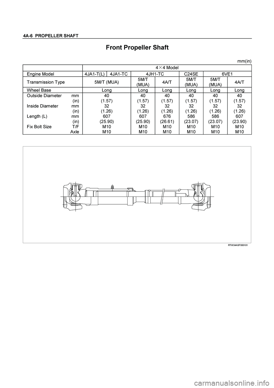
4A-6 PROPELLER SHAFT
Front Propeller Shaft
mm(in)
4�
4 Model
Engine Model 4JA1-T(L) 4JA1-TC 4JH1-TC C24SE 6VE1
Transmission Type 5M/T (MUA) 5M/T
(MUA) 4A/T 5M/T
(MUA) 5M/T
(MUA) 4A/T
Wheel Base Long Long Long Long Long Long
Outside Diameter mm 40 40 40 40 40 40
(in) (1.57) (1.57) (1.57) (1.57) (1.57) (1.57)
Inside Diameter mm 32 32 32 32 32 32
(in) (1.26) (1.26) (1.26) (1.26) (1.26) (1.26)
Length (L) mm 607 607 676 586 586 607
(in) (25.90) (25.90) (26.61) (23.07) (23.07) (23.90)
Fix Bolt Size T/F M10 M10 M10 M10 M10 M10
Axle M10 M10 M10 M10 M10 M10
RTW34ASF000101
Page 171 of 4264

REAR AXLE 4B-7
REAR AXLE ASSEMBLY
General Description
A03R300001
The rear axle assembly is of the semi–floating type in
which the vehicle weight is carried on the axle
housing .
The center line of the pinion gear is below the center
line of the ring gear (hypoid drive).
All parts necessary to transmit power from the
propeller shaft to the rear wheels are enclosed in a
banjo type axle housing.
The 220 mm (8.6 in) ring gear rear axle uses a
conventional ring and pinion gear set to transmit the
driving force of the engine to the rear wheels. This
gear set transfers this driving force at a 90 degree
angle from the propeller shaft to the drive shafts.
The axle shafts are supported at the wheel end of the
shaft by a double tapered roller bearing.
The pinion gear is supported by two tapered roller
bearings. The pinion depth is set by a shim pack
located between the gear end of the pinion and the
roller bearing that is pressed onto the pinion. The
pinion bearing preload is set by crushing a collapsible
spacer between the bearings in the axle housing.
The ring gear is bolted onto the differential cage with
12 bolts.
The differential cage is supported in the axle housing
by two tapered roller bearings. The differential and ring
gear are located in relationship to the pinion by using
selective shims and spacers between the bearing and
the differential cage. To move the ring gear, shims are
deleted from one side and an equal amount are added
to the other side. These shims are also used to
preload the bearings which are pressed onto the
differential cage. Two bearing caps are used to hold
the differential into the rear axle housing.
The differential is used to allow the wheels to turn at
different rates of speed while the rear axle continues
to transmit the driving force. This prevents tire
scuffing when going around corners and prevents
premature wear on internal axle parts.
The rear axle is sealed with a pinion seal, a seal at
each axle shaft end, and by a liquid gasket between
the differential carrier and the axle housing