Page 277 of 4264
FRONT WHEEL DRIVE 4C1-57
FRONT HUB AND DISC
(4�
�� �4 Manual Locking Hub Model)
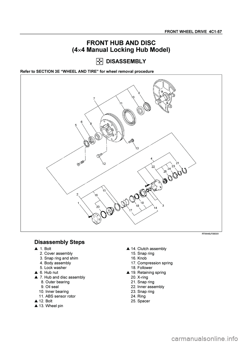
DISASSEMBLY
Refer to SECTION 3E “WHEEL AND TIRE” for wheel removal procedure
RTW440LF000301
Disassembly Steps
�
1. Bolt
2. Cover assembly
3. Snap ring and shim
4. Body assembly
5. Lock washer
�
6. Hub nut
�
7. Hub and disc assembly
8. Outer bearing
9. Oil seal
10. Inner bearing
11. ABS sensor rotor
�
12. Bolt
�
13. Wheel pin
�
14. Clutch assembly
15. Snap ring
16. Knob
17. Compression spring
18. Follower
�
19. Retaining spring
20. X-ring
21. Snap ring
22. Inner assembly
23. Snap ring
24. Ring
25. Spacer
Page 279 of 4264
FRONT WHEEL DRIVE 4C1-59
12. Bolt
13. Wheel Pin ; Front Hub
(1) Scribe mark on hub to disc before disassembly to insure
proper assembly.
(2) Drive out the ABS sensor rotor using a metal bar and
hammer through the two bolt holes.
�
Discard the used ABS sensor rotor
Refer to the section Brake.
(3) Clamp hub and disc assembly in vise using protective pads
and remove six (6) disc to hub retaining bolts.
(4) Place hub on a suitable work surface and remove wheel
studs, as required, using a hammer.
Page 280 of 4264
4C1-60 FRONT WHEEL DRIVE
INSPECTION AND REPAIR
Make necessary correction or parts replacement if wear, damage or any other abnormal conditions are found
through inspection.
For inspection and servicing of disc caliper, and relative parts, and ABS parts, refer to Section Brakes.
�
Hub
� Hub bearing, oil seal
�
Knuckle spindle
�
Disc
�
Caliper
�
ABS sensor rotor
�
Cap, Hub flange, Shim, Snap ring
�
Free wheeling hub parts (Option)
� Clutch, Knob, follower, inner, ring and
spring
Visual Check
Check the following parts for wear, damage or other abnormal
conditions.
Page 281 of 4264
FRONT WHEEL DRIVE 4C1-61
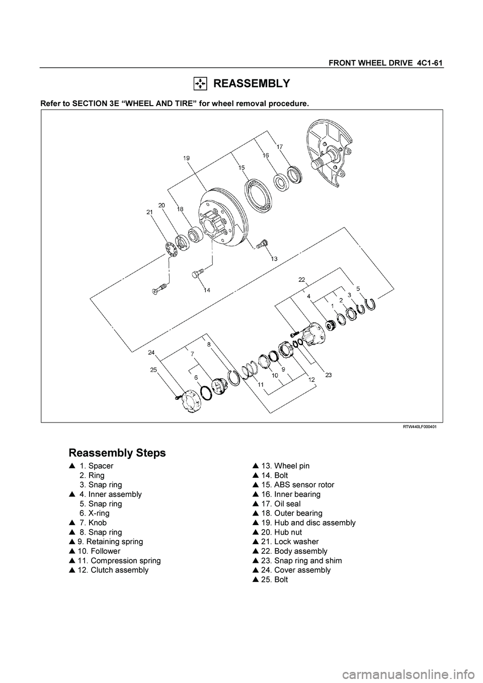
REASSEMBLY
Refer to SECTION 3E “WHEEL AND TIRE” for wheel removal procedure.
RTW440LF000401
Reassembly Steps
�
1. Spacer
2. Ring
3. Snap ring
�
4. Inner assembly
5. Snap ring
6. X-ring
�
7. Knob
�
8. Snap ring
�
9. Retaining spring
�
10. Follower
�
11. Compression spring
�
12. Clutch assembly
�
13. Wheel pin
�
14. Bolt
�
15. ABS sensor rotor
�
16. Inner bearing
�
17. Oil seal
�
18. Outer bearing
�
19. Hub and disc assembly
�
20. Hub nut
�
21. Lock washer
�
22. Body assembly
�
23. Snap ring and shim
�
24. Cover assembly
�
25. Bolt
Page 283 of 4264
FRONT WHEEL DRIVE 4C1-63
13. Wheel Pin
(1) Place hub on a wood workbench or a block of wood,
approx. 6” by 6” to protect the wheel stud ends and threads.
(2) Install wheel stud using a hammer.
Be sure wheel stud is started squarely and seats
completely.
(3) Align index marks and install hub to disc.
14. Bolt
Torque N�
m (kgf�
m/lb�
ft)
103 �
10 (10.5 �
1/75.9 �
7.2)
15. ABS sensor rotor
(1) Set a new ABS sensor rotor, if replacement is required.
(2) Install the ABS sensor rotor in the hub, using special tools.
Installer : 5-8840-2789-0
Grip : 5-8840-0007-0
Refer to the section Brake.
16. Inner Bearing
Outer race ; outer bearing
Install the outer race by driving it into the hub.
Installer : 5-8840-2119-0
(J-36829)
Grip : 5-8840-0007-0
(J-8092)
Page 298 of 4264
4C1-78 FRONT WHEEL DRIVE
ITEM NO. ILLUSTRATION PART NO. PART NAME
5-8840-2789-0
ABS sensor rotor installer
Page 317 of 4264

BRAKE CONTROL SYSTEM 5A-1
SECTION 5A
BRAKE CONTROL SYSTEM
CONTENTS
Service Precaution ............................................................................................................. 5A-4
General Description ........................................................................................................... 5A-5
EHCU, Brake Pipe Diagram .......................................................................................... 5A-6
Hydraulic Unit (H/U)....................................................................................................... 5A-7
Normal Braking ......................................................................................................... 5A-8
Pressure Isolation (Pressure Maintain) .................................................................. 5A-9
Pressure Reduction .................................................................................................. 5A-10
Brake Release ........................................................................................................... 5A-11
Circuit Diagram.............................................................................................................. 5A-12
Connector List ............................................................................................................... 5A-13
Part Location ................................................................................................................. 5A-15
EHCU Pin-outs ............................................................................................................... 5A-17
System Components ..................................................................................................... 5A-19
Electronic Hydraulic Control Unit (EHCU) .............................................................. 5A-19
ABS Warning Lamp .................................................................................................. 5A-19
Wheel Speed Sensor (WSS)..................................................................................... 5A-19
G-Sensor ................................................................................................................... 5A-19
Normal and Anti-lock Braking ................................................................................. 5A-19
Electronic Brake-force Distribution (EBD) System ................................................ 5A-20
Brake Pedal Travel.................................................................................................... 5A-20
Acronyms and Abbreviations ....................................................................................... 5A-20
General Diagnosis ............................................................................................................. 5A-20
General Information ...................................................................................................... 5A-20
ABS Service Precautions.............................................................................................. 5A-20
Computer System Service Precautions....................................................................... 5A-21
General Service Precautions........................................................................................ 5A-21
Note on Intermittents .................................................................................................... 5A-21
Test Driving ABS Complaint Vehicles ......................................................................... 5A-21
"ABS and Brake" Warning Lamp ................................................................................. 5A-22
Normal Operation .......................................................................................................... 5A-22
Page 318 of 4264
 Warning Lamp.......................................................................................... 5A-22
Tech 2 Scan Tool ...............................")
5A-2 BRAKE CONTROL SYSTEM
Brake (EBD) Warning Lamp.......................................................................................... 5A-22
Tech 2 Scan Tool ........................................................................................................... 5A-23
DATA LIST (Tech 2) ....................................................................................................... 5A-26
Actuator Test (Tech 2)................................................................................................... 5A-27
Diagnostic Trouble Codes................................................................................................. 5A-30
Diagnosis By "ABS" Warning Lamp Illumination Pattern .............................................. 5A-32
Basic Diagnostic Flow Chart ............................................................................................ 5A-35
Basic Inspection Procedure .............................................................................................. 5A-37
1. Basic Inspection of Service Brake ........................................................................... 5A-37
2. Ground Inspection .................................................................................................... 5A-37
Wheel Speed Sensor Inspection Procedure .................................................................... 5A-38
Symptom Diagnosis........................................................................................................... 5A-39
ABS Works Frequently But Vehicle Does Not Decelerate ......................................... 5A-39
Uneven Braking Occurs While ABS Works ................................................................. 5A-40
The Wheels Are Locked ................................................................................................ 5A-40
Brake Pedal Feed Is Abnormal ..................................................................................... 5A-41
Braking Sound (From EHCU) Is Heard
While Not Braking ....................................................................................................... 5A-42
No ABS Warning Lamp ................................................................................................. 5A-43
DTC C0221 (Flash Code 21) Front Right Wheel Speed Sensor
Short Circuit or Circuit Open ......................................................................................... 5A-44
DTC C0222 (Flash Code 22) Front Right Wheel Speed Sensor Incorrect Signal.......... 5A-46
DTC C0223 (Flash Code 23) Front Right Wheel Speed Sensor
Signal - Tooth Chipping................................................................................................... 5A-48
DTC C0225 (Flash Code 25) Front Left Wheel Speed Sensor Short Circuit or
Circuit Open .................................................................................................................... 5A-50
DTC C0226 (Flash Code 26) Front Left Wheel Speed Sensor Incorrect Signal ............ 5A-52
DTC C0227 (Flash Code 27) Front Left Wheel Speed Sensor Signal - Tooth
Chipping ........................................................................................................................... 5A-54
DTC C0231 (Flash Code 31) Rear Right Wheel Speed Sensor Short Circuit or
Circuit Open .................................................................................................................... 5A-56
DTC C0232 (Flash Code 32) Rear Right Wheel Speed Sensor Incorrect Signal ........... 5A-58
DTC C0233 (Flash Code 33) Rear Right Wheel Speed Sensor Signal - Tooth
Chipping ........................................................................................................................... 5A-60
 Scribe mark on hub to disc before disassembly to insure
proper assembly.
(2) Drive out the ABS sensor rotor using a metal bar")

 Place hub on a wood workbench or a block of wood,
approx. 6” by 6” to protect the wheel stud ends and threads.
(2) Install wheel stud using a hamm")
