Page 3185 of 4264
.
Torque: 27 N�
�� �m (2.8 kg�
�� �m/20 lb�
�� �ft)
225R300001
8. Install top gear bearing snap ring (10) and counter
front")
MANUAL TRANSMISSION 7B1-21
7. Install the speedometer sensor (2).
Torque: 27 N�
�� �m (2.8 kg�
�� �m/20 lb�
�� �ft)
225R300001
8. Install top gear bearing snap ring (10) and counter
front bearing snap ring (8).
�
Use a pair of snap ring pliers to install the snap
rings to the mainshaft and countershaft.
�
The snap rings must be fully inserted into the
bearing snap ring groove.
9. Front cover with oil seal (9).
Front Cover Oil Seal Replacement
�
Remove the oil seal from the front cover.
�
Apply engine oil to a new oil seal outer
circumference.
�
Apply recommended grease to the oil seal lip.
�
Use the oil seal installer 5-8840-0026-0 to install
the oil seal to the front cover.
220R3000020
10. Install a new gasket and front cover (9) to the
transmission case.
NOTE: Take care not to damage the oil seal.
Notes When Tightening the Bolt:
�
After cleaning the bolt hole, dry it thoroughly with air.
�
After cleaning the screw face of a removed bolt or
new one, dry it thoroughly. Apply recommended
liquid gasket (LOCTITE 242) or its equivalent before
tightening it.
Tighten six front cover bolts to the specified torque.
Torque: 25 N�
�� �
m (2.6 kg�
�� �
m/19 lb�
�� �
ft)
11. Apply molybdenum disulfide type grease to the
areas as shown in the figure and install shift fork (7).
(Diesel engine, C24NE)
F07L100026
Page 3494 of 4264
 MODEL
Front suspension Type Independent wishbone arms, coil spring
with stabilizer bar.
Coil spring")
3C-2 FRONT SUSPENSION
MAIN DATA AND SPECIFICATIONS
4�
�� �2 (EXCEPT HIGH RIDE SUSPENSION) MODEL
Front suspension Type Independent wishbone arms, coil spring
with stabilizer bar.
Coil spring Spring Rate 4JH1-TC / 4JA1-TC / 4JA1-L (ENGINE); 9.62 kg/mm
(94.3 N/mm)
C24SE (ENGINE); 7.94 kg/mm (77.9 N/mm)
Type Gas-sealed. Hydraulic, double acting
Stroke 116.5 mm (4.59 in)
Compressed length 284.0 mm (11.18 in)
Front shock absorber
Extended length 400.5 mm (15.77 in)
Stabilizer bar Diameter 25.0 mm (0.98 in)
4�
�� �2 (HIGH RIDE SUSPENSION) MODEL
Front suspension Type Independent wishbone arms, torsion bar spring
with stabilizer bar.
Length 1142 mm (44.96 in) Torsion bar spring
Diameter 29.0 mm (1.14 in)
Type Gas-sealed. Hydraulic, double acting
Stroke 121.0 mm (4.76 in)
Compressed length 257.0 mm (10.12 in)
Front shock absorber
Extended length 378.0 mm (14.88 in)
Stabilizer bar Diameter 26.0 mm (1.02 in)
4�
�� �4 MODEL
Front suspension Type Independent wishbone arms, torsion bar spring
with stabilizer bar.
Length 1142 mm (44.96 in) Torsion bar spring
Diameter 29.0 mm (1.14 in)
Type Gas-sealed. Hydraulic, double acting
Stroke 121.0 mm (4.76 in)
Compressed length 257.0 mm (10.12 in)
Front shock absorber
Extended length 378.0 mm (14.88 in)
Stabilizer bar Diameter 26.0 mm (1.02 in)
Page 3558 of 4264
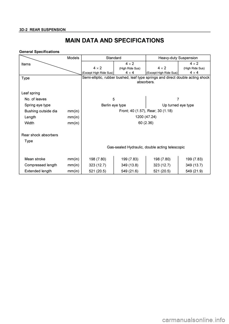
3D-2 REAR SUSPENSION
MAIN DATA AND SPECIFICATIONS
General Specifications
Models Standard Heavy-duty Suspension
Items
4 � 2
(Except High Ride Sus)
4 � 2
(High Ride Sus)
4
� 4
4 � 2 (Except High Ride Sus) 4 � 2
(High Ride Sus)
4
� 4
Type Semi-elliptic, rubber bushed, leaf type springs and direct double acting shock
absorbers.
Leaf spring
No. of leaves
5 7
Spring eye type
Berlin eye type Up turned eye type
Bushing outside dia mm(in) Front; 40 (1.57), Rear; 30 (1.18)
Length mm(in) 1200 (47.24)
Width mm(in) 60 (2.36)
Rear shock absorbers
Type
Gas-sealed Hydraulic, double acting telescopic
Mean stroke mm(in)
198 (7.80) 199 (7.83) 198 (7.80) 199 (7.83)
Compressed length mm(in)
323 (12.7) 349 (13.8) 323 (12.7) 349 (13.7)
Extended length mm(in)
521 (20.5) 549 (21.6) 521 (20.5) 549 (21.9)
Page 3845 of 4264
 7A4–37
Diaassembly, Inspection and
Reassembly of minor Components
NOTE: The instructions here are organized so that you
work on only one component group at a time.
This wi")
UNIT REPAIR (AW30–40LE) 7A4–37
Diaassembly, Inspection and
Reassembly of minor Components
NOTE: The instructions here are organized so that you
work on only one component group at a time.
This will help avoid confusion from similar-looking parts
of different subassemblies being on your workbench at
the same time.
The component groups are inspected and repaired from
the converter housing side.
As much as possible, complete the inspection, repair
and reassembly before proceeding to the nex t
component group. If a component group cannot be
reassembled because parts are being ordered, be sure
to keep all parts of that group in separate container
while proceeding with disassembly, inspection, repair
and reassembly of other component groups.
Recommended ATF type DEXRON III.
General Cleaning Notes:
1. All disassembled parts should be washed clean and
any fluid passages and holes should be blown
through with compressed air.
2. When using compressed air to dry parts, always aim
away from yourself to prevent accidentally spraying
automatic transmission fluid in your face.
3. The recommended automatic transmission fluid
should be used for cleaning.
Parts Arrangement:
1. After cleaning, the parts should be arranged in
proper order to allow performing inspection, repairs,
and reassembly with efficiency.
2. When disassembling a valve body, be sure to keep
each valve together with the corresponding spring.
3. New brakes and clutches that are to be used for
replacement must be soaked in transmission fluid
for at least thirty minutes before assembly.
General Assembly:
1. All oil seal rings, clutch discs, clutch plates, rotating
parts, and sliding surfaces should be coated with
transmission fluid prior to reassembly.
2. All gaskets and rubber O-ring should be replaced.
3. Make sure that the ends of a snap ring are not
aligned with one of the cutouts and are installed in
the groove correctly.
4. If a worn bushing is to be replaced, the
subassembly containing that bushing must be
replaced.
5. Check thrust bearings and races for wear or
damage. Replace if necessary.
6. Use petroleum jelly or vaseline to keep parts in
place.