Page 615 of 4264
CLUTCH 7C-13
4JA1T(L)
RTW47CMF000401
4JA1TC/4JH1TC
Page 616 of 4264
7C-14 CLUTCH
C24SE
RTW37CSF0003
The driven plate assembly consists of the plate and the facing.
The plate consists of the clutch center, the cushioning plate and the torsion springs.
The facing is riveted to both sides of the cushioning plate.
The cushioning plate provides a longer service life by minimizing wear and vibration at the clutch contact surfaces.
Page 617 of 4264

Strength 4.")
CLUTCH 7C-15
TORQUE SPECIFICATION
STANDARD BOLTS
The torque values given in the following table should be applied where a particular torque is not specified.
N�
m (kgf�
m/lb ft)
Strength 4.8/4T 7T 8.8 9.8/9T
Class Refined Non-Refined
Bolt Identifi-
cation
Bolt
Diameter�
�� �
Pitch (mm)
-
M6 � 1.0 6 (0.6 / 52 lb.in) 7 (0.7 / 61 lb.in) 8 (0.8 / 69 lb.in) -
M8 � 1.25 13 (1.3 / 113 lb.in) 17 (1.7 / 12) 20 (2.0 / 14) 24 (2.4 / 17)
M10 � 1.25 27 (2.8 / 20) 37 (3.8 / 27) 42 (4.3 / 31) 50 (5.1 / 37)
M12 � 1.25 61 (6.3 / 45) 76 (7.8 / 56) 87 (8.9 / 64) 95 (9.7 / 70)
M14 �1.5 96 (9.8 / 71) 116 (11.8 / 85) 133 (13.6 / 98) 142 (14.5 / 105)
M16 � 1.5 130 (13.3 / 96) 170 (17.3 / 125) 193 (19.7 / 143) 200 (20.4 / 148)
M18 � 1.5 188 (19.2 / 139) 244 (24.9 / 180) 278 (28.3 / 205) 287 (29.3 / 212)
M20 � 1.5 258 (26.3 / 190) 337 (34.4 / 249) 385 (39.3 / 284) 396 (40.4 / 292)
M22 � 1.5 332 (33.9 / 245) 453 (46.3 / 335) 517 (52.7 / 381) 530 (54.1 / 391)
M24 � 2.0 449 (45.8 / 331) 570 (58.2 / 421) 651 (66.3 / 480) 692 (70.6 / 511)
* M10 � 1.5 26 (2.7 / 20) 36 (3.7 / 27) 41 (4.2 / 30) 48 (4.9 / 35)
* M12 � 1.75 57 (5.8 / 42) 71 (7.2 / 52) 80 (8.2 / 59) 89 (9.1 / 66)
* M14 � 2.0 89 (9.1 / 66) 110 (11.2 / 81) 125 (12.7 / 92) 133 (13.6 / 98)
* M16 � 2.0 124 (12.7 / 92) 162 (16.5 / 119) 185 (18.9 / 137) 191 (19.5 / 141)
Flange Bolt M6 � 1.0 7 (0.7 / 61 lb.in) 8 (0.8 / 69 lb.in) 9 (0.9 / 78 lb.in) -
M8
� 1.25 15 (1.5 / 11) 19 (1.9 / 14) 22 (2.2 / 16) 26 (2.7 / 20)
M10 � 1.25 31 (3.2 / 23) 41 (4.2 / 30) 47 (4.8 / 35) 56 (5.7 / 41)
M12 � 1.25 69 (7.0 / 51) 85 (8.7 / 63) 97 (9.9 / 72) 106 (10.8 / 78)
M14
� 1.5 104 (10.6 / 77) 126 (12.8 / 93) 144 (14.6 / 106) 154 (15.7 / 114)
M16 � 1.5 145 (14.8 / 127) 188 (19.2 / 139) 214 (21.8 / 158) 221 (22.5 / 163)
M18 � 1.5 - - - -
M20
� 1.5 - - - -
M22 � 1.5 - - - -
M24 � 2.0 - - - -
* M10
� 1.5 30 (3.1 / 22) 40 (4.1 / 30) 46 (4.7 / 34) 54 (5.5 / 40)
* M12 � 1.75 64 (6.5 / 47) 78 (8.0 / 58) 89 (9.1 / 66) 99 (10.1 / 73)
* M14 � 2.0 97 (9.9 / 72) 119 (12.1 / 88) 135 (13.8 / 99.7) 144 (14.7 / 107)
* M16
� 2.0 137 (14.0 / 101) 178 (18.2 / 132) 203 (20.7 / 132) 210 (21.5 / 155)
The asterisk * indicates that the bolts are used for female-threaded parts that are made of soft materials such as
casting, etc.
FLARE NUTS
Pipe diameter mm (in) Torque
N
�
�� �m (kgf
�
�� �m / lb ft) Pipe diameter mm (in) Torque N
�
�� �m (kgf
�
�� �m / lb ft)
4.76 (0.187) 16 (1.6 / 12) 10.00 (0.394) 54 (5.5 / 40)
6.35 (0.250) 26 (2.7 / 20) 12.00 (0.472) 88 (9.0 / 65)
8.00 (0.315) 44 (4.5 / 33) 15.00 (0.591) 106 (10.8 / 78)
Standard Hex.
Head Bolt
Page 618 of 4264
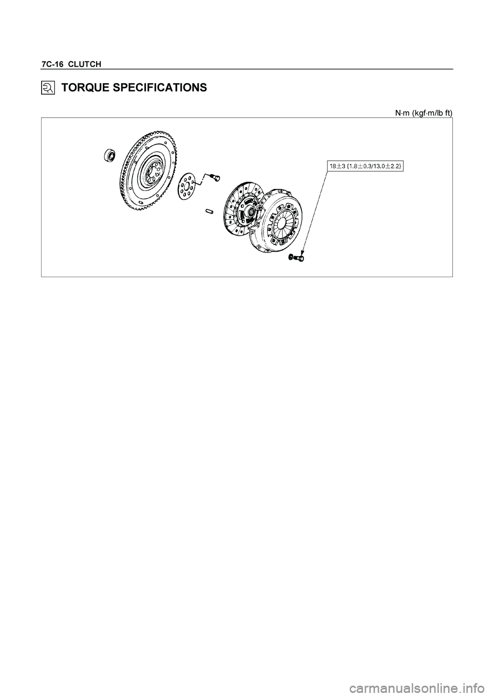
7C-16 CLUTCH
TORQUE SPECIFICATIONS
N�m (kgf�m/lb ft)
Page 619 of 4264
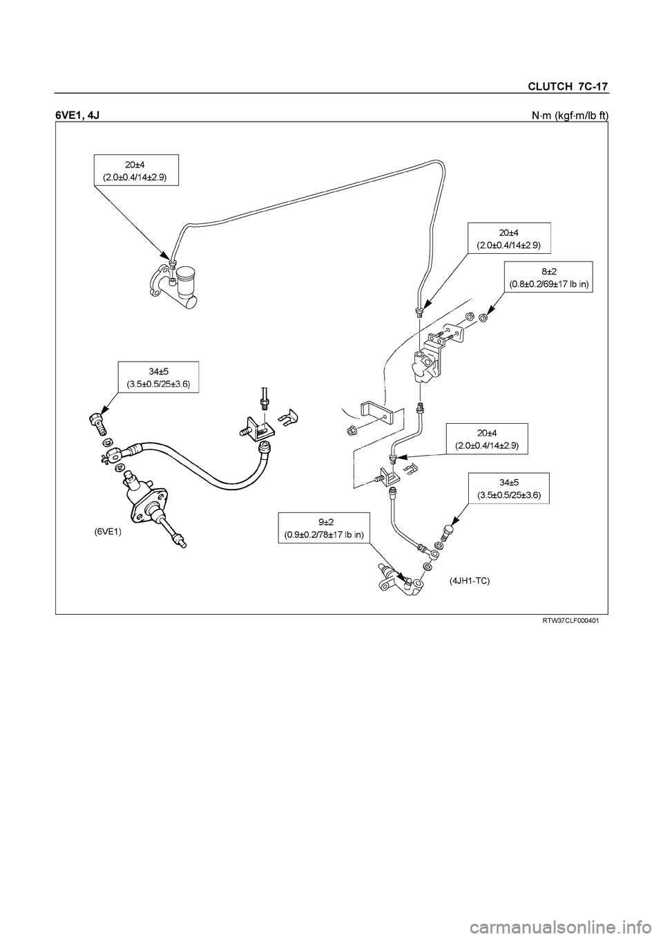
CLUTCH 7C-17
6VE1, 4J
N�
m (kgf�
m/lb ft)
RTW37CLF000401
Page 620 of 4264
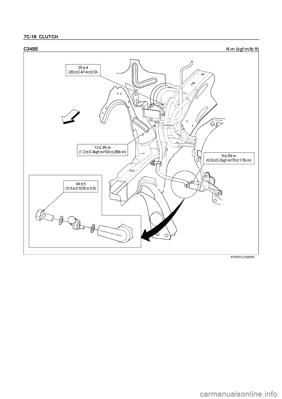
7C-18 CLUTCH
C24SE
N�
m (kgf�
m/lb ft)
RTW37CLF000301
Page 621 of 4264
CLUTCH 7C-19
SERVICING
Servicing refers to general maintenance procedures to be performed by qualified service personnel.
CLUTCH PEDAL PLAY
Inspection
Depress the clutch pedal lightly by hand, and measure to
determine if the free play is within the standard value.
Pedal Free Play mm(in)
H 5.0-15.0 (0.2-0.6)
Adjustment of the clutch switch (or stopper bolt)
Turn the clutch switch or stopper bolt
1 until the switch bolt
or
stopper bolt
just touches the clutch pedal arm.
Adjust clutch switch
or stopper bolt
by backing it out half a turn,
and measure the clearance (L) between the clutch pedal arm
and the clutch switch bolt end
or stopper bolt.
Lock the lock nut
2.
Connect clutch switch connector.
Clutch switch and clutch pedal
Clearance mm(in)
(L) 0.5-1.5 (0.020-0.059)
Page 622 of 4264
7C-20 CLUTCH
AIR BLEEDING
Bleed air from clutch operating cylinder according to the
following procedure.
Carefully monitor fluid level at master cylinder during bleeding
operation.
1. Set the paking brake.
2. Top up reservoir with recommended brake fluid.
3. Connect a transparent vinyl tube to air bleeder valve.
4. Fully depress clutch pedal several times.
5. With clutch pedal depressed, open bleeder valve to release
air.
6. Close bleeder valve.
7. Repeat steps 5 through 6 above until brake fluid flows from
air bleeder valve without air bubbles.
8. Bleed air from clutch damper according to the above
procedure.
9. Repeat the above bleeding procedure until the air
completely removed.

RTW47CMF000401
4JA1TC/4JH1TC")