Page 1981 of 4264
STARTING AND CHARGING SYSTEM (6VE1 3.5L) 6D3-9
Inspection and Repair
Repair or replace necessary parts if extreme wear or
damage is found during inspection.
Armature
Measure the outer diameter of commutator, and replace
with a new one if it is out of the limit.
Standard: 30 mm (1.1811 in)
Limit: 29 mm (1.1417 in)
065RS014
Check for continuity between segment and segment on
the commutator. Replace commutator if there is no
continuity (i.e., disconnected).
065RS015
Check for continuity between commutator and shaft.
Also, check for continuity between commutator and
armature core, armature core and shaft. Replace
commutator if there is continuity (i.e., internally
grounded).
065RS016
Measure runout of the commutator with a dial gauge.
Repair or replace, if it exceeds the limit.
Limit: 0.4 mm (0.0157 in)
065RY00061
Page 1982 of 4264
6D3-10 STARTING AND CHARGING SYSTEM (6VE1 3.5L)
Polish the commutator surface with sandpaper #500 to
#600 if it is rough.
065RW012
Measure the depth of insulator in commutator. Replace,
if it is below the limit.
Standard: 0.45 mm to 0.75 mm (0.0177 in to
0.0295 in)
Limit: 0.2 mm (0.008 in)
065RY00070
Legend
(1) Insulator
(2) Depth of Insulator
(3) Commutator Segments
Brush
Measure the length of brush.
Replace with a new one, if it is below the limit.
Standard: 15 mm (0.5906 in)
Limit: 11 mm (0.43 in)
065RW014
Brush Holder
Check for continuity between brush holder (+) (4) and
base (–). Replace, if there is continuity (i.e., insulation is
broken).
065RW015
Page 1983 of 4264
 6D3-11
Brush Spring
Use spring balancer to measure the spring setting force
when remove the spring from the brush.
Standard: 17.65–23.54 N (38.9–51.9")
STARTING AND CHARGING SYSTEM (6VE1 3.5L) 6D3-11
Brush Spring
Use spring balancer to measure the spring setting force
when remove the spring from the brush.
Standard: 17.65–23.54 N (38.9–51.9 lb)
Limit: 11.77 N (25.9 lb)
Magnetic Switch
Temporarilly connect the magnetic switch between the
overrunning clutch and housing.
Perform the steps described below in 3 to 5 seconds.
1. Pull in test
Connect the ground (-) to terminal C and magnetic
switch body.
Verify that the pinion pulls out when the battery (+)
pole is connected to terminal 50.
065R100017
2. Hold in test
Observe that the pinion stays when the lead wire is
disconnected from terminal C.
065R100018
3. Return test
Connect the ground (-) to terminal 50 and magnetic
switch body.
Verify that the pinion pulls out when the battery (+)
pole is connected to terminal C and the pinion
pulls away when the lead wire is disconnected from
terminal 50.
065R100019
Field Coil
1. Check for continuity between the end of the field coil
and yoke body.
Replace the field coil, if there is continuity.
065RY00065
Page 1984 of 4264
6D3-12 STARTING AND CHARGING SYSTEM (6VE1 3.5L)
2. Check continuity between the lead wire of terminal
C and brush.
Replace the yoke assembly, if there is no continuity.
065RY00066
Overrunning Clutch
1. Visual check for excessive wear or damage.
2. Test the pinion rotation, it must rotate smoothly
when rotated clockwise and it shouldn't rotate when
turned counterclockwise.
065RY00067
Bearing
1. Inspect excessive wear or damage.
Replace the bearing if an abnormal noise is heard
under normal operating condition.
065RY00068
Reassembly
To install, follow the removal steps in the reverse order,
noting the following points:
Grease application places
Bearing in rear cover
Gears in reduction gear
Sliding portion of pinion
Page 1985 of 4264
STARTING AND CHARGING SYSTEM (6VE1 3.5L) 6D3-13
Main Data and Specifications
General Specifications
Model ADX4IH
Rating
Voltage 12 V
Output 1.4 Kw
Time 30 sec
Number of teeth of pinion 9
Rotating direction(as viewed from pinion) Clockwise
Weight(approx.) 3.8kg (8.4lb)
No–load characteristics
Voltage /Current 11.5V/90A or less
Speed 3000rpm or more
Load characteristics
Voltage/current 8.5V/350A or less
Torque 13.2Nm (1.35kgm/9.77lb in.) or more
Speed 1000rpm or more
Locking characteristics
Voltage/current 2.4V/500A or less
Torque 11.8N�
�� �m (1.2kg�
�� �m/8.68lb in) or more
Page 1986 of 4264
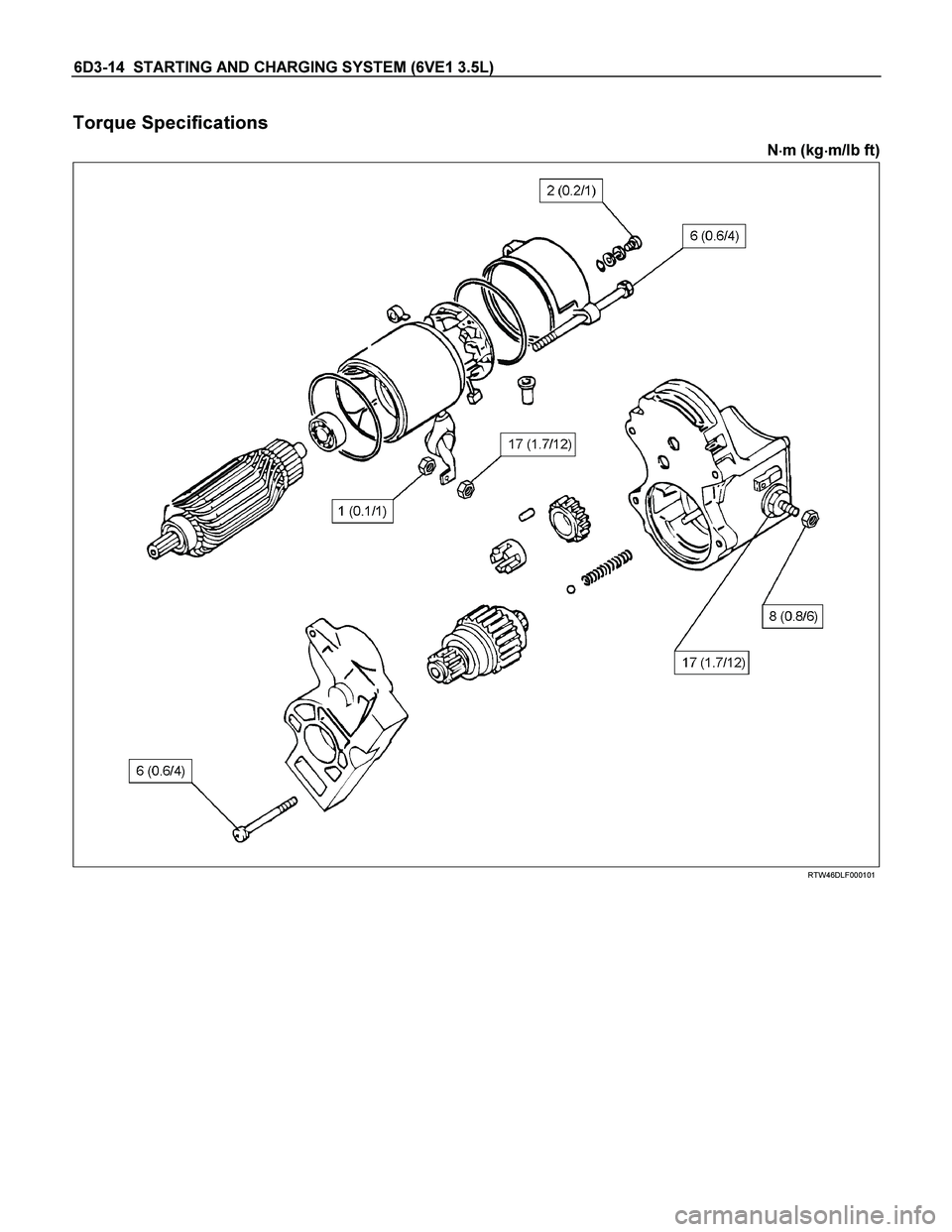
6D3-14 STARTING AND CHARGING SYSTEM (6VE1 3.5L)
Torque Specifications
N�
�� �m (kg�
�� �m/lb ft)
RTW46DLF000101
Page 1987 of 4264
 6D3-15
Charging System
General Description
The IC integral regulator charging system and its main
components are connected as shown in illustration.
The")
STARTING AND CHARGING SYSTEM (6VE1 3.5L) 6D3-15
Charging System
General Description
The IC integral regulator charging system and its main
components are connected as shown in illustration.
The regulator is a solid state type and it is mounted
along with the brush holder assembly inside the
generator installed on the rear end cover.
The generator does not require particular maintenance
such as voltage adjustment.
The rectifier connected to the stator coil has eigh
t
diodes to transform AC voltage into DC voltage.
This DC voltage is connected to the output terminal o
f
generator.
General On–Vehicle Inspection
The operating condition of charging system is indicated
by the charge warning lamp. The warning lamp comes
on when the starter switch is turned to “ON" position.
The charging system operates normally if the lamp
goes off when the engine starts.
If the warning lamp shows abnormality or i
f
undercharged or overcharged battery condition is
suspected, perform diagnosis by checking the charging
system as follows:
1. Check visually the belt and wiring connector.
2. With the engine stopped, turn the stator switch to
“ON" position and observe the warning lamp.
If lamp does not come on:
Disconnect wiring connector from generator, and
ground the terminal “L" on connector side.
If lamp comes on:
Repair or replace the generator.
F06RW009
Page 1988 of 4264

Generator
Removal
1. Disconnect battery ground cable.
2. Move drive belt tensioner to loose side using
wrench then remove drive belt (1).
3. Di")
6D3-16 STARTING AND CHARGING SYSTEM (6VE1 3.5L)
Generator
Removal
1. Disconnect battery ground cable.
2. Move drive belt tensioner to loose side using
wrench then remove drive belt (1).
3. Disconnect the wire from terminal “B" and
disconnect the connector (4).
4. Remove generator fixing bolt (3).
5. Remove generator assembly (2).
060RW002
Inspection
1. Disconnect the wiring connector from generator.
2. With the engine stopped, turn starter switch to “ON"
and connect a voltmeter between connecto
r
terminal L (2) and ground or between terminal IG (1)
and ground.
066RW001
If voltage is not present, the line between battery
and connector is disconnected and so requires
repair.
3. Reconnect the wiring connector to the generator,
run the engine at middle speed, and turn off all
electrical devices other than engine.
4. Measure battery voltage. If it exceeds 16V, repair o
r
replace the generator.
5. Connect an ammeter to output terminal o
f
generator, and measure output current under load
by turning on the other electrical devices (eg.,
headlights). At this time, the voltage must not be
less than 13V.
Installation
1. Install generator assembly to the position to be
installed.
2. Install generator assembly and tighten the fixing
bolts to the specified torque.
Torque:
M10 bolt: 52 N�
�� �m (5.3 kg�
�� �m/38 lb ft)
M8 bolt: 25 N�
�� �m (2.5 kg�
�� �m/18 lb ft)
3. Connect wiring harness connector and direc
t
terminal “B".
4. Move drive belt tensioner to loose side using
wrench, then install drive belt to normal position.
5. Reconnect battery ground cable.
 6D3-9
Inspection and Repair
Repair or replace necessary parts if extreme wear or
damage is found during inspection.
Armature
Measure the outer diameter of")

Polish the commutator surface with sandpaper #500 to
#600 if it is rough.
065RW012
Measure the depth of insulator in commutator. Replace,
if it")

2. Check continuity between the lead wire of terminal
C and brush.
Replace the yoke assembly, if there is no continuity.
065RY00066
Overru")
 6D3-13
Main Data and Specifications
General Specifications
Model ADX4IH
Rating
Voltage 12 V
Output 1.4 Kw
Time 30 sec
Number of teeth of pinion")