Page 2539 of 4264
 6C-15
Filler Neck
Removal
1. Remove the fuel tank.
NOTE: Refer to \"Fuel Tank\" in this section.
2. Put a marking the following point as the filler neck
assembly is restored.")
ENGINE FUEL (C24SE) 6C-15
Filler Neck
Removal
1. Remove the fuel tank.
NOTE: Refer to "Fuel Tank" in this section.
2. Put a marking the following point as the filler neck
assembly is restored.
� Each joint area of the hose (to restore axial
direction and insertion length of the hose)
� Each fasten area of the clamp (to restore axial
direction and position of the clamp)
� Each bolt in the clamp (to restore fasten length
of bolt in the clamp)
� The band clip (to restore position and fasten
length of the band clip)
NOTE: Cover end of each hose and pipe to prevent any
dust entering.
Installation
1. Align each marking and restore the following point.
� Each joint area of the hose (Restore axial
direction and insertion length of the hose)
� Each fasten area of the clamp (Restore axial
direction and position of the clamp)
� Each bolt in the clamp (Restore fasten length o
f
bolt in the clamp)
Torque: 2.5 N�
�� �m (0.25 kg�
�� �m / 2 lb ft) … filler neck
side except flat deck model.
� The band clip (Restore position and fasten
length of the band clip)
2. Install the fuel tank.
NOTE: Refer to "Fuel Tank" in this section.
Fuel Gauge Unit
Removal and Installation
As for removal and installation of the Fuel Gauge Unit,
refer to “Fuel Tank" of this section 6C as the fuel gauge
unit is combined with the fuel pump and sende
r
assembly.
Page 2541 of 4264
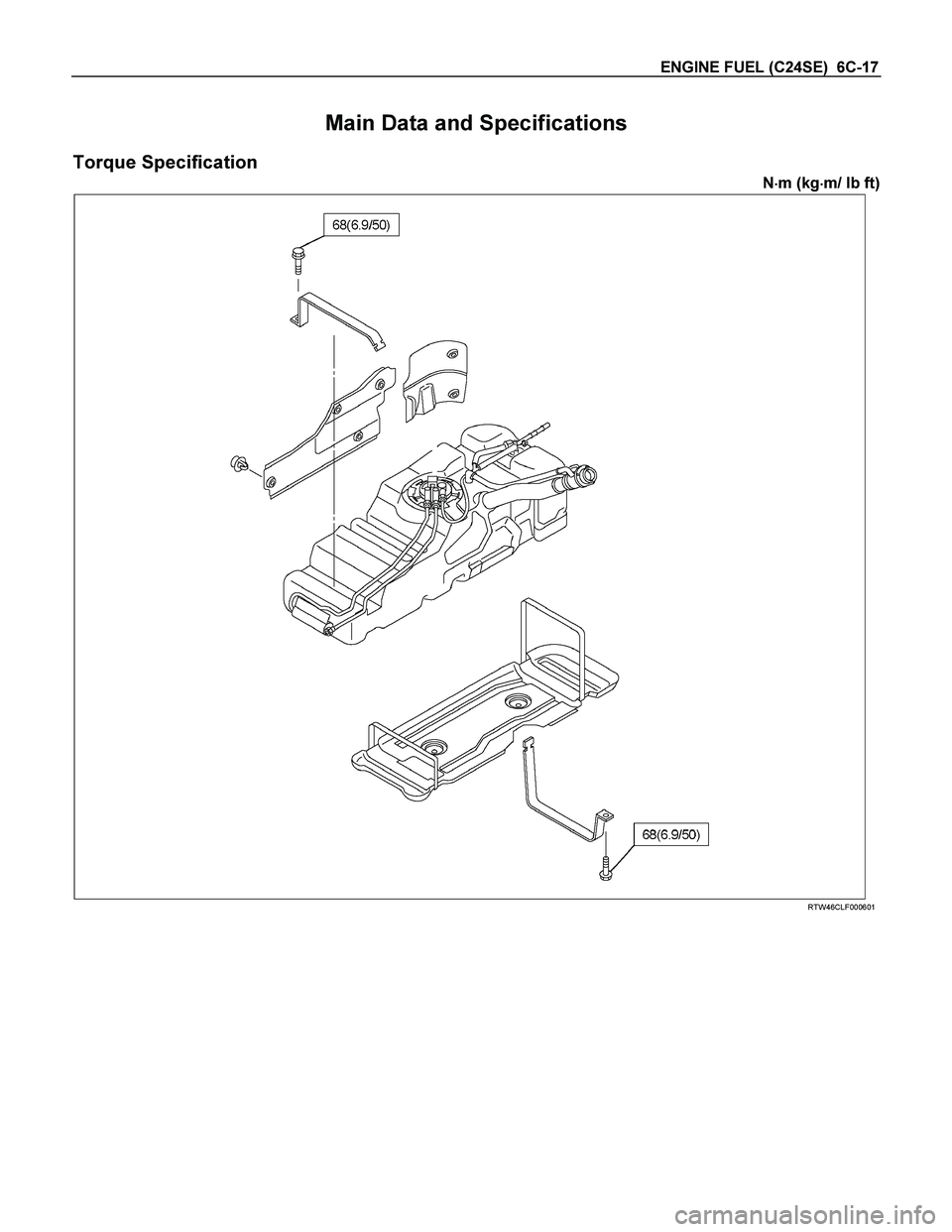
ENGINE FUEL (C24SE) 6C-17
Main Data and Specifications
Torque Specification
N�
�� �m (kg�
�� �m/ lb ft)
RTW46CLF000601
Page 2544 of 4264

6D1-2 ENGINE ELECTRICAL
Battery
General Description
There are six battery fluid caps on top of the battery.
These are covered by a paper label.
The battery is completely sealed except for the six small vent
holes on the side. These vent holes permit the escape of small
amounts of gas generated by the battery.
This type of battery has the following advantages over
conventional batteries:
1. There is no need to add water during the entire service life
of the battery.
2. The battery protects itself against overcharging.
The battery will refuse to accept an extensive charge.
(A conventional battery will accept an excessive charge,
resulting in gassing and loss of battery fluid.)
3. The battery is much less vulnerable to self discharge than a
conventional type battery.
Service Precaution
CAUTION:
Always use the correct fastener in the proper location.
When you replace a fastener, use ONLY the exact part
number for that application. ISUZU will call out those
fasteners that require a replacement after removal. ISUZU
will also call out the fasteners that require thread lockers
or thread sealant. UNLESS OTHERWISE SPECIFIED, do
not use supplemental coatings (Paints, greases, or other
corrosion inhibitors) on threaded fasteners or fastener
joint interfaces. Generally, such coatings adversely affect
the fastener torque and the joint clamping force, and may
damage the fastener. When you install fasteners, use the
correct tightening sequence and specifications. Following
these instructions can help you avoid damage to parts
and systems.
Page 2550 of 4264

6D2-2 IGNITION SYSTEM
General Description
Ignition is done by the Ignition Module that fires.
Since the cylinder on exhaust stroke requires less energy to
fire its spark plug, energy from the ignition coils can be utilized
to fire the mating cylinder on compression stroke.
A notch in the timing disc on the crankshaft activates the crank
angle sensor which then sends information such as firing order
and starting timing of ignition coil to the ECM.
By receiving signals such as crank position, engine speed,
water temperature and Manifold Absolute Pressure (MAP), the
ECM controls the ignition timing.
Service Precaution
CAUTION:
Always use the correct fastener in the proper location.
When you replace a fastener, use ONLY the exact part
number for that application. ISUZU will call out those
fasteners that require a replacement after removal. ISUZU
will also call out the fasteners that require thread lockers
or thread sealant. UNLESS OTHERWISE SPECIFIED, do
not use supplemental coatings (Paints, greases, or other
corrosion inhibitors) on threaded fasteners or fastener
joint interfaces. Generally, such coatings adversely affect
the fastener torque and the joint clamping force, and may
damage the fastener. When you install fasteners, use the
correct tightening sequence and specifications. Following
these instructions can help you avoid damage to parts
and systems.
Diagnosis
Refer to Section Drivability and Emissions for the diagnosis to
electronic ignition system (El system).
Ignition Coil
Removal
1. Disconnect battery ground cable.
2. Disconnect the Ignition coil connector.
3. Remove the ignition coil.
Installation
1. Install the ignition coil.
Connect ignition coil connector and ignition coil, then tighten
bolt to the specified torque.
Torque: 20 N�
�� �m (2.0 kgf�
�� �m)
2. Connect battery ground cable.
Page 2552 of 4264
6D2-4 IGNITION SYSTEM
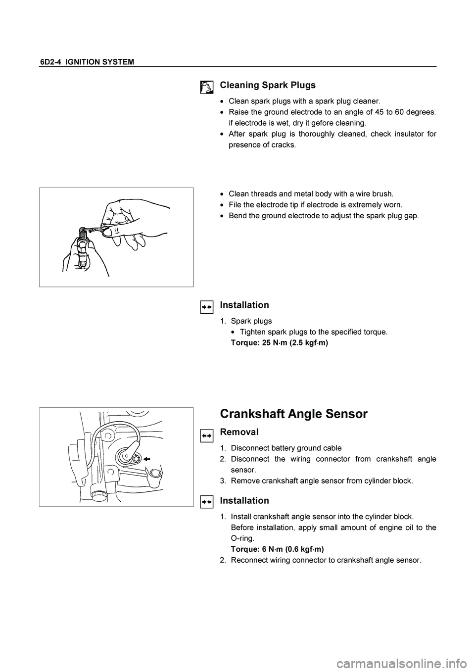
Cleaning Spark Plugs
�
Clean spark plugs with a spark plug cleaner.
� Raise the ground electrode to an angle of 45 to 60 degrees.
if electrode is wet, dry it gefore cleaning.
�
After spark plug is thoroughly cleaned, check insulator for
presence of cracks.
�
Clean threads and metal body with a wire brush.
�
File the electrode tip if electrode is extremely worn.
�
Bend the ground electrode to adjust the spark plug gap.
Installation
1. Spark plugs
�
Tighten spark plugs to the specified torque.
Torque: 25 N
�
�� �m (2.5 kgf
�
�� �m)
Crankshaft Angle Sensor
Removal
1. Disconnect battery ground cable
2. Disconnect the wiring connector from crankshaft angle
sensor.
3. Remove crankshaft angle sensor from cylinder block.
Installation
1. Install crankshaft angle sensor into the cylinder block.
Before installation, apply small amount of engine oil to the
O-ring.
Torque: 6 N
�
�� �m (0.6 kgf
�
�� �m)
2. Reconnect wiring connector to crankshaft angle sensor.
Page 2553 of 4264
IGNITION SYSTEM 6D2-5
Main Data and Specifications
General Specifications
Ignition System
Ignition Form Electronic Ignition System (El system) with Crankshaft angle Sensor
Spark Plug
Type
No. of Coils and Type
Coil Location
Torque Electronic Spark Control
2 Solid State
Engine-mounted
20 N�m (2.0 kgf�m)
Page 2556 of 4264

6D3-2 STARTING AND CHARGING SYSTEM
Starting System
General Description
Cranking Circuit
The cranking system consists of a battery, starter, starter
switch, starter relay, etc. These main components are
connected.
Starter
The cranking system employs a magnetic type reduction
starter in which the motor shaft is also used as a pinion shaft.
When the starter switch is turned on, the contacts of magnetic
switch are closed, and the armature rotates. At the same time,
the plunger is attracted, and the pinion is pushed forward by
the shift lever to mesh with the ring gear.
Then, the ring gear runs to start the engine. When the engine
starts and the starter switch is turned off, the plunger returns,
the pinion is disengaged from the ring gear, and the armature
stops rotation. When the engine speed is higher than the
pinion, the pinion idles, so that the armature is not driven.
Service Precaution
CAUTION:
Always use the correct fastener in the proper location.
When you replace a fastener, use ONLY the exact part
number for that application. ISUZU will call out those
fasteners that require a replacement after removal. ISUZU
will also call out the fasteners that require thread lockers
or thread sealant. UNLESS OTHERWISE SPECIFIED, do
not use supplemental coatings (Paints, greases, or other
corrosion inhibitors) on threaded fasteners or fastener
joint interfaces. Generally, such coatings adversely affect
the fastener torque and the joint clamping force, and may
damage the fastener. When you install fasteners, use the
correct tightening sequence and specifications. Following
these instructions can help you avoid damage to parts
and systems.
Diagnosis
Condition Possible cause Correction
Starter does not run Charging failure Repair charging system
Battery Failure Replace Battery
Terminal connection failure Repair or replace terminal connector
and/or wiring harness
Starter switch failure Repair or replace starter switch
Starter failure Repair or replace starter
Page 2557 of 4264
STARTING AND CHARGING SYSTEM 6D3-3
Starter
Removal
1. Remove the battery ground cable.
2. Remove harness connectors (1) and (2).
3. Remove bolts from starter.
Installation
1. Install starter assembly.
2. Install mounting bolts and tighten bolts to specified torque.
Torque: 51 N
�
�� �m (5.2 kgf
�
�� �m)
3. Connect harness.
4. Reconnect the battery ground cable.
 with Crankshaft angle Sensor
Spark Plug
Type")
 and (2).
3. Remove bolts from starter.
Installatio")