Page 2478 of 4264
6A-58 ENGINE MECHANICAL (C24SE)
Clean
Plastigage from journals.
Lightly coat journals and bearings with engine oil.
Installation
Install bearing cap and shell using new bolts.
Torque - Angle Method
Main bearing cap bolt - 60 N�
m (6.1 kgf�
m) +40�
to 50�
.
Con-rod bearing cap bolts - 35 N�
m (3.9 kgf�
m) +45�
.
2.Micrometer and gauge method.
Crankshaft removed.
Installation
1. Install caps and bearing shells to con-rods and cylinder
block.
Measure
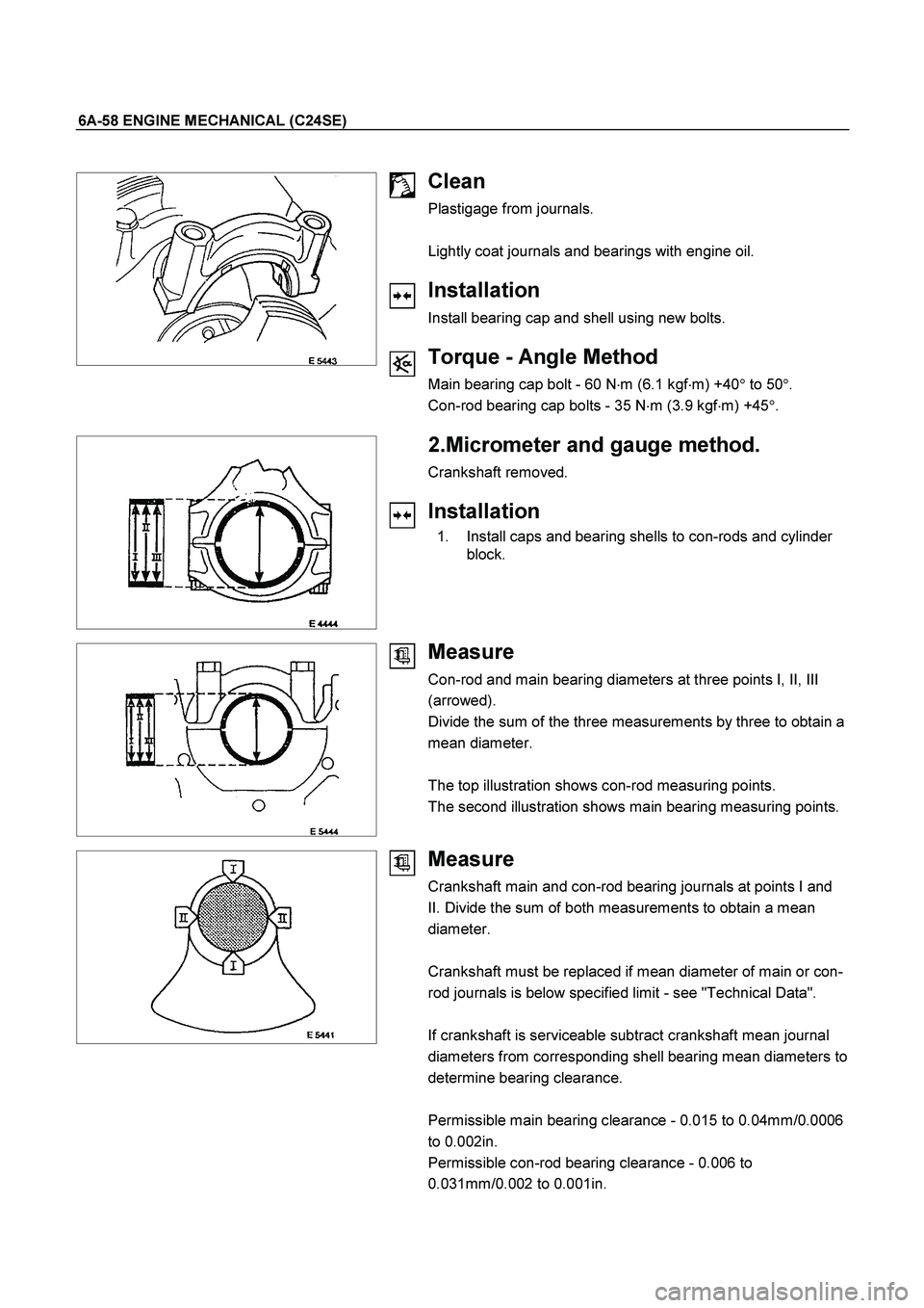
Con-rod and main bearing diameters at three points I, II, III
(arrowed).
Divide the sum of the three measurements by three to obtain a
mean diameter.
The top illustration shows con-rod measuring points.
The second illustration shows main bearing measuring points.
Measure
Crankshaft main and con-rod bearing journals at points I and
II. Divide the sum of both measurements to obtain a mean
diameter.
Crankshaft must be replaced if mean diameter of main or con-
rod journals is below specified limit - see "Technical Data".
If crankshaft is serviceable subtract crankshaft mean journal
diameters from corresponding shell bearing mean diameters to
determine bearing clearance.
Permissible main bearing clearance - 0.015 to 0.04mm/0.0006
to 0.002in.
Permissible con-rod bearing clearance - 0.006 to
0.031mm/0.002 to 0.001in.
Page 2499 of 4264
ENGINE MECHANICAL (C24SE) 6A-79
Cylinder Head (continued)
Valve System
Valve lifter valve play compensator
(hydraulic)
Valve rotators
(inlet or outlet) outlet
Valve play
(warm or cold) inlet mm 0
outlet mm 0
Cylinder head height mm 280.3�0.075
Cylinder head bottom, face parallelism mm 0.05
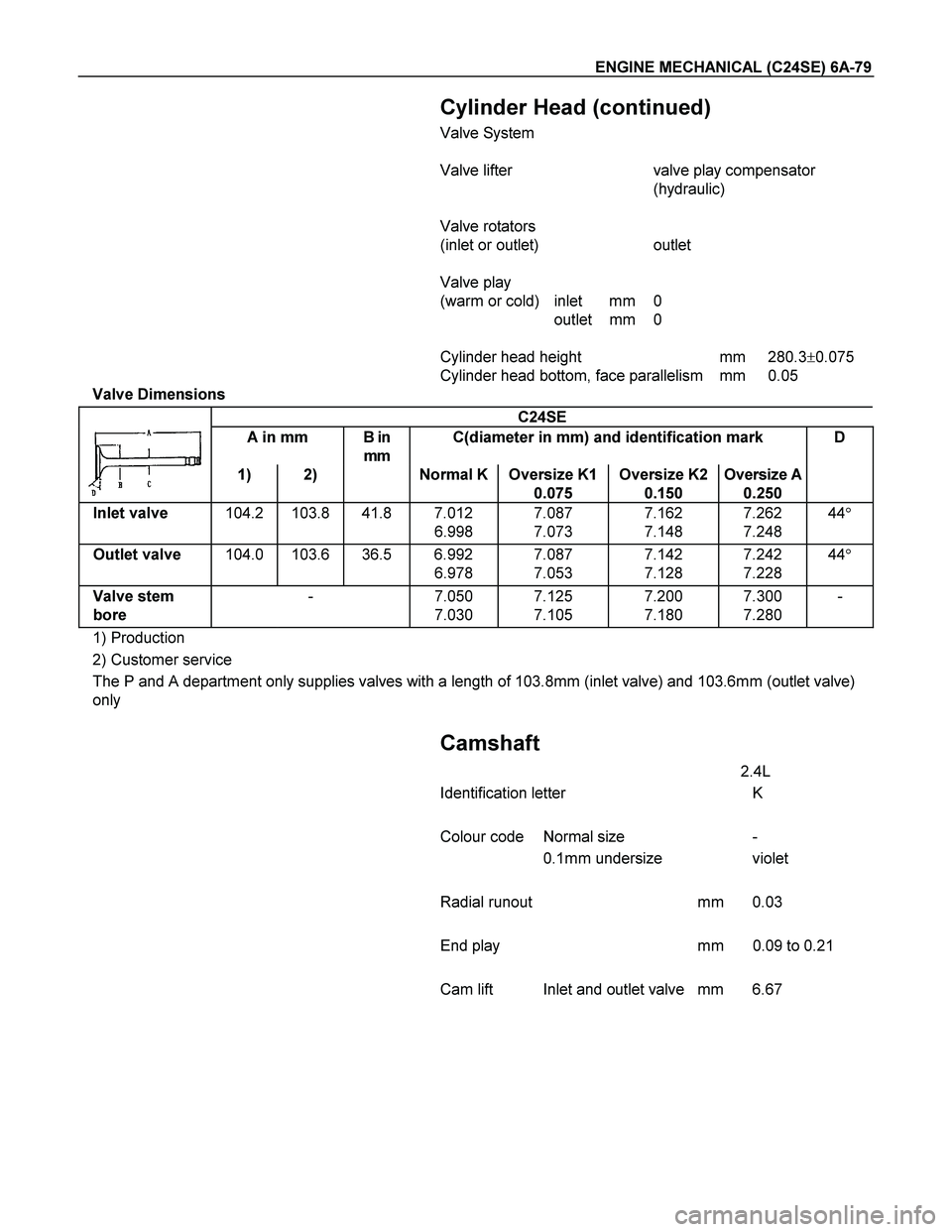
Valve Dimensions
C24SE
A in mm B in
mm C(diameter in mm) and identification mark D
1) 2) Normal K Oversize K1
0.075 Oversize K2
0.150 Oversize A
0.250
Inlet valve 104.2 103.8 41.8 7.012
6.998 7.087
7.073 7.162
7.148 7.262
7.248 44�
Outlet valve 104.0 103.6 36.5 6.992
6.978 7.087
7.053 7.142
7.128 7.242
7.228 44�
Valve stem
bore - 7.050
7.030 7.125
7.105 7.200
7.180 7.300
7.280 -
1) Production
2) Customer service
The P and A department only supplies valves with a length of 103.8mm (inlet valve) and 103.6mm (outlet valve)
only
Camshaft
2.4L
Identification letter K
Colour code Normal size -
0.1mm undersize violet
Radial runout mm 0.03
End play mm 0.09 to 0.21
Cam lift Inlet and outlet valve mm 6.67
Page 2501 of 4264
ENGINE MECHANICAL (C24SE) 6A-81
Crankshaft, Cylinder Block
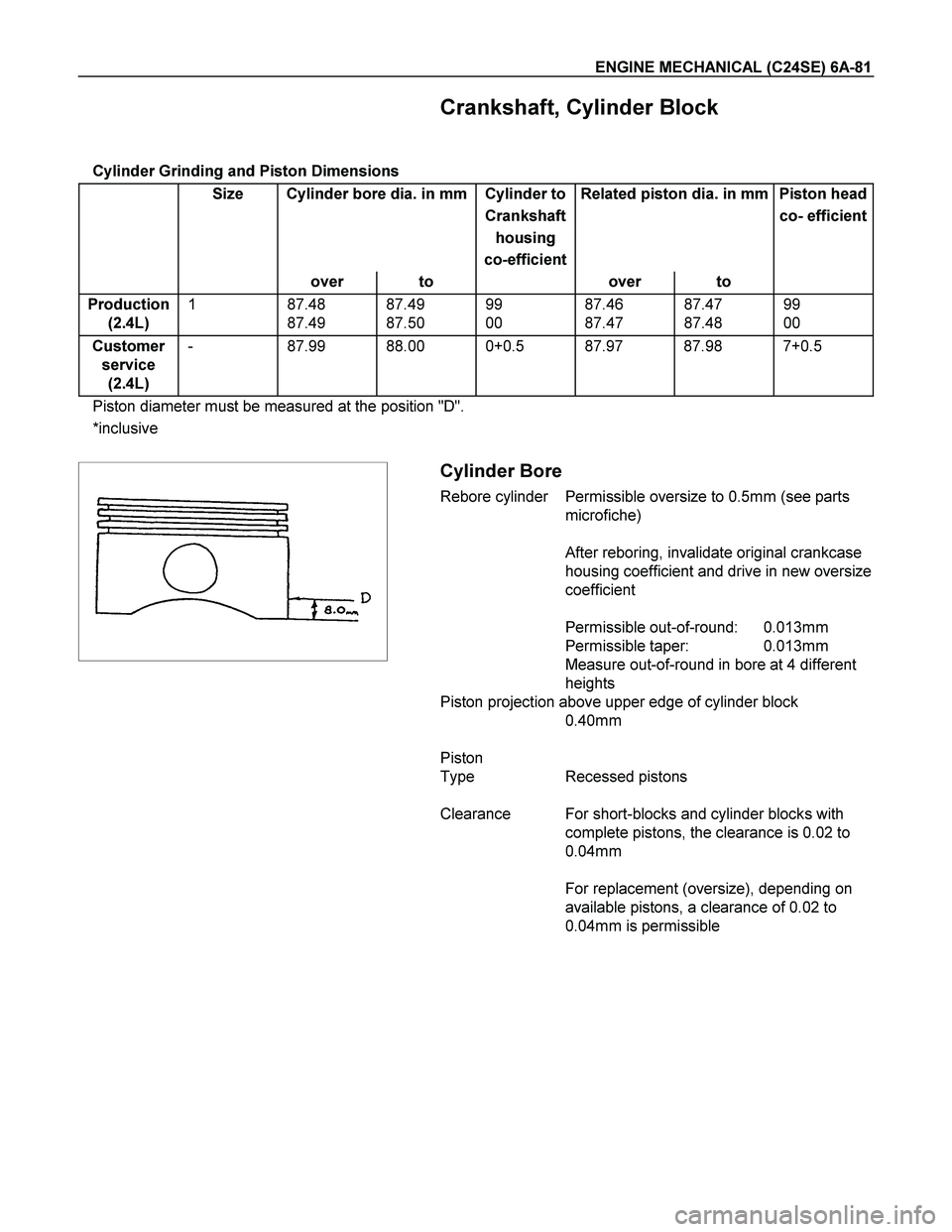
Cylinder Grinding and Piston Dimensions
Size Cylinder bore dia. in mm Cylinder to Related piston dia. in mm Piston head
Crankshaft co- efficient
housing
co-efficient
over to over to
Production
(2.4L) 1 87.48
87.49 87.49
87.50 99
00 87.46
87.47 87.47
87.48 99
00
Customer
service
(2.4L) - 87.99 88.00 0+0.5 87.97 87.98 7+0.5
Piston diameter must be measured at the position "D".
*inclusive
Cylinder Bore
Rebore cylinder Permissible oversize to 0.5mm (see parts
microfiche)
After reboring, invalidate original crankcase
housing coefficient and drive in new oversize
coefficient
Permissible out-of-round: 0.013mm
Permissible taper: 0.013mm
Measure out-of-round in bore at 4 different
heights
Piston projection above upper edge of cylinder block
0.40mm
Piston
Type Recessed pistons
Clearance For short-blocks and cylinder blocks with
complete pistons, the clearance is 0.02 to
0.04mm
For replacement (oversize), depending on
available pistons, a clearance of 0.02 to
0.04mm is permissible
Page 2503 of 4264
ENGINE MECHANICAL (C24SE) 6A-83
Crankshaft, Cylinder Block (continued)
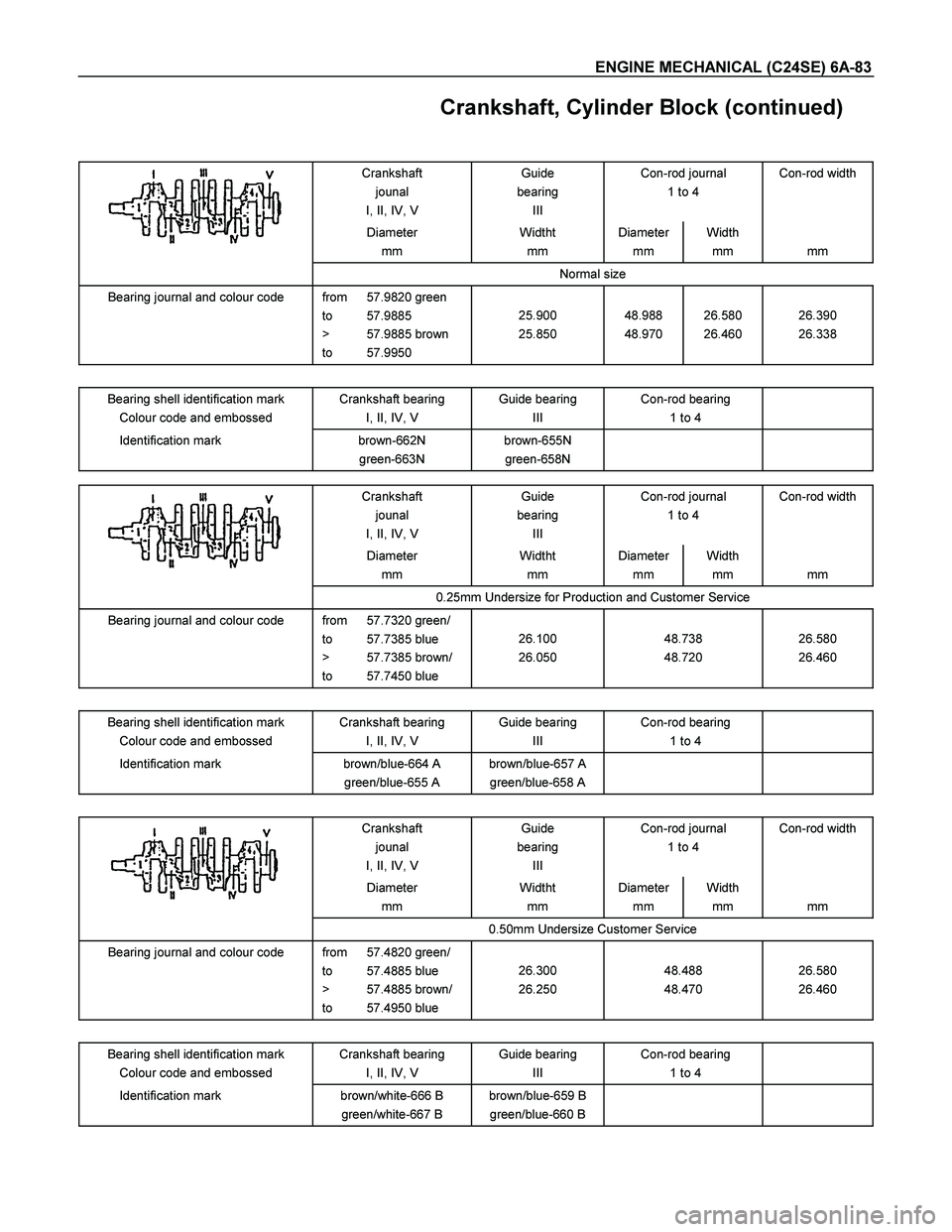
Crankshaft
jounal
I, II, IV, V Guide
bearing
III Con-rod journal
1 to 4 Con-rod width
Diameter
mm Widtht
mm Diameter
mm Width
mm
mm
Normal size
Bearing journal and colour code from 57.9820 green
to 57.9885
> 57.9885 brown
to 57.9950
25.900
25.850
48.988
48.970
26.580
26.460
26.390
26.338
Bearing shell identification mark
Colour code and embossed Crankshaft bearing
I, II, IV, V Guide bearing
III Con-rod bearing
1 to 4
Identification mark brown-662N
green-663N brown-655N
green-658N
Crankshaft
jounal
I, II, IV, V Guide
bearing
III Con-rod journal
1 to 4 Con-rod width
Diameter
mm Widtht
mm Diameter
mm Width
mm
mm
0.25mm Undersize for Production and Customer Service
Bearing journal and colour code from 57.7320 green/
to 57.7385 blue
> 57.7385 brown/
to 57.7450 blue
26.100
26.050
48.738
48.720
26.580
26.460
Bearing shell identification mark
Colour code and embossed Crankshaft bearing
I, II, IV, V Guide bearing
III Con-rod bearing
1 to 4
Identification mark brown/blue-664 A
green/blue-655 A brown/blue-657 A
green/blue-658 A
Crankshaft
jounal
I, II, IV, V Guide
bearing
III Con-rod journal
1 to 4 Con-rod width
Diameter
mm Widtht
mm Diameter
mm Width
mm
mm
0.50mm Undersize Customer Service
Bearing journal and colour code from 57.4820 green/
to 57.4885 blue
> 57.4885 brown/
to 57.4950 blue
26.300
26.250
48.488
48.470
26.580
26.460
Bearing shell identification mark
Colour code and embossed Crankshaft bearing
I, II, IV, V Guide bearing
III Con-rod bearing
1 to 4
Identification mark brown/white-666 B
green/white-667 B brown/blue-659 B
green/blue-660 B
Page 2505 of 4264
ENGINE MECHANICAL (C24SE) 6A-85
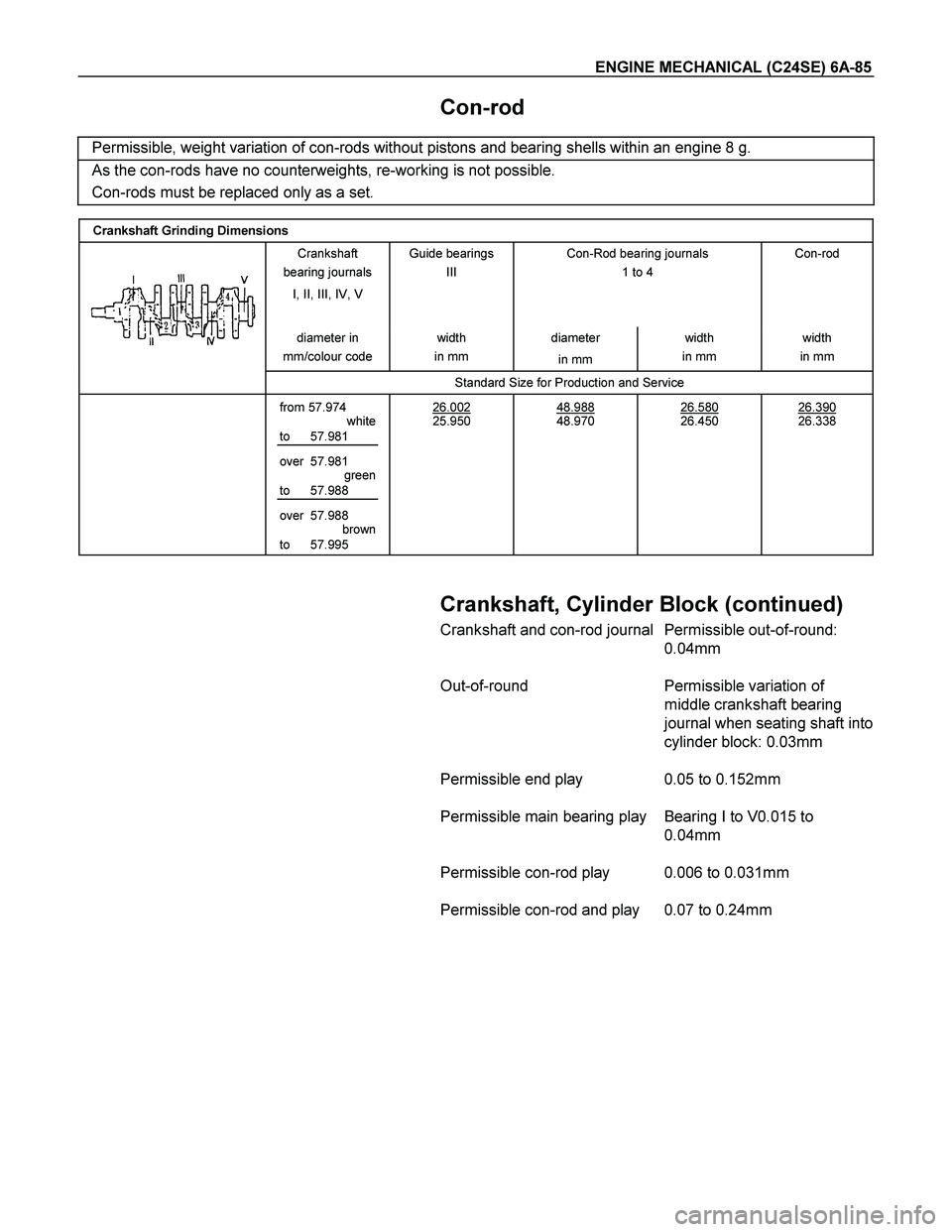
Con-rod
Permissible, weight variation of con-rods without pistons and bearing shells within an engine 8 g.
As the con-rods have no counterweights, re-working is not possible.
Con-rods must be replaced only as a set.
Crankshaft Grinding Dimensions
Crankshaft
bearing journals
I, II, III, IV, V
Guide bearings
III
Con-Rod bearing journals
1 to 4
Con-rod
diameter in
mm/colour code width
in mm diameter
in mm width
in mm width
in mm
Standard Size for Production and Service
from 57.974
white
to 57.981
over 57.981
green
to 57.988
over 57.988
brown
to 57.995 26.002
25.950
48.988
48.970
26.580
26.450
26.390
26.338
Crankshaft, Cylinder Block (continued)
Crankshaft and con-rod journal Permissible out-of-round:
0.04mm
Out-of-round Permissible variation of
middle crankshaft bearing
journal when seating shaft into
cylinder block: 0.03mm
Permissible end play 0.05 to 0.152mm
Permissible main bearing play Bearing I to V0.015 to
0.04mm
Permissible con-rod play 0.006 to 0.031mm
Permissible con-rod and play 0.07 to 0.24mm
Page 2508 of 4264
6A-88 ENGINE MECHANICAL (C24SE)
SPECIAL SERVICE TOOLS
ITEM NO. ILLUSTRATION PART NO. PART NAME
5-8840-2634-0
Aligner
5-8840-2593-0
Cutter set
5-8840-2594-0
Spring Compressor
5-8840-0451-0
Installer
5-8840-0452-0
Remover / Installer
5-8840-2596-0
Distance Gauge
5-8840-0455-0
Assembly Sleeves
5-8840-2597-0
Installer
5-8840-0457-0
Remover / Installer
5-8840-0468-0
Remover / Installer
Page 2511 of 4264
ENGINE COOLING 6B-1
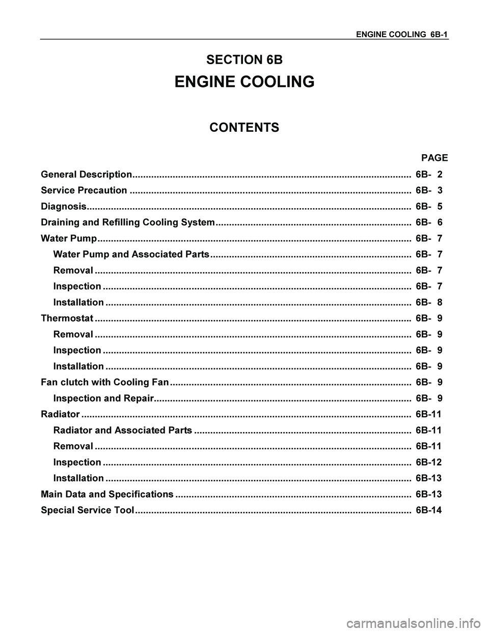
SECTION 6B
ENGINE COOLING
CONTENTS
PAGE
General Description........................................................................................................ 6B- 2
Service Precaution......................................................................................................... 6B- 3
Diagnosis......................................................................................................................... 6B- 5
Draining and Refilling Cooling System ......................................................................... 6B- 6
Water Pump ..................................................................................................................... 6B- 7
Water Pump and Associated Parts ........................................................................... 6B- 7
Removal ...................................................................................................................... 6B- 7
Inspection ................................................................................................................... 6B- 7
Installation .................................................................................................................. 6B- 8
Thermostat ...................................................................................................................... 6B- 9
Removal ...................................................................................................................... 6B- 9
Inspection ................................................................................................................... 6B- 9
Installation .................................................................................................................. 6B- 9
Fan clutch with Cooling Fan .......................................................................................... 6B- 9
Inspection and Repair................................................................................................ 6B- 9
Radiator ........................................................................................................................... 6B-11
Radiator and Associated Parts ................................................................................. 6B-11
Removal ...................................................................................................................... 6B-11
Inspection ................................................................................................................... 6B-12
Installation .................................................................................................................. 6B-13
Main Data and Specifications ........................................................................................ 6B-13
Special Service Tool ....................................................................................................... 6B-14
Page 2513 of 4264
ENGINE COOLING 6B-3
Service Precaution
CAUTION:
Always use the correct fastener in the proper location.
When you replace a fastener, use ONLY the exact part
number for that application. ISUZU will call out those
fasteners that require a replacement after removal. ISUZU
will also call out the fasteners that require thread lockers
or thread sealant. UNLESS OTHERWISE SPECIFIED, do
not use supplemental coatings (Paints, greases, or other
corrosion inhibitors) on threaded fasteners or fastener
joint interfaces. Generally, such coatings adversely affect
the fastener torque and the joint clamping force, and may
damage the fastener. When you install fasteners, use the
correct tightening sequence and specifications. Following
these instructions can help you avoid damage to parts
and systems.
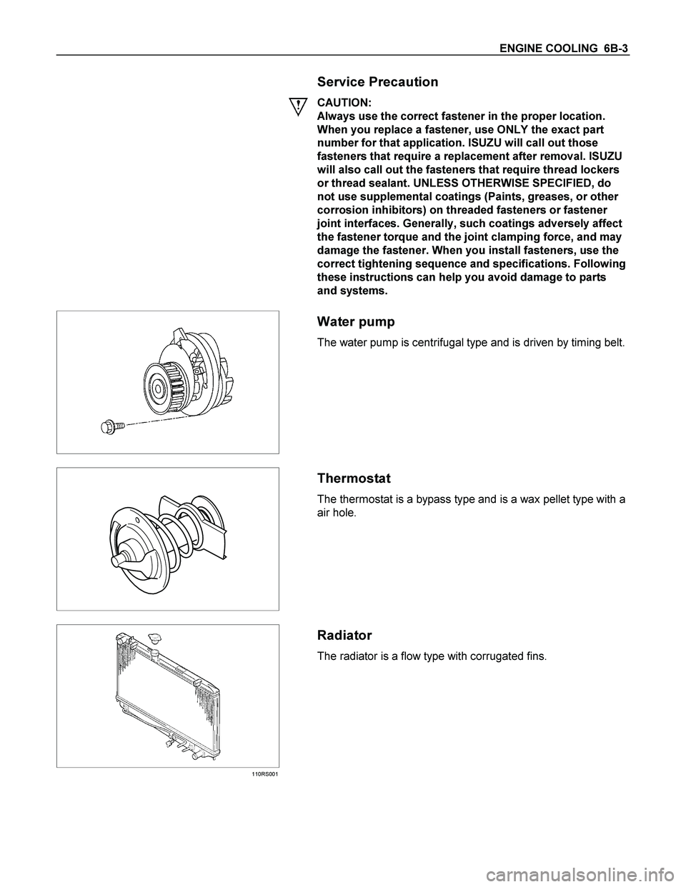
Water pump
The water pump is centrifugal type and is driven by timing belt.
Thermostat
The thermostat is a bypass type and is a wax pellet type with a
air hole.
110RS001
Radiator
The radiator is a flow type with corrugated fins.