Page 252 of 4264
4C1-32 FRONT WHEEL DRIVE
5. Cross Pin
(1) Be sure to install the cross pin so that it is in alignment with
the lock pin hole in the differential cage.
(2)
Adjust the backlash between the side gear and the pinion
gear.
mm(in)
Backlash 0.10 - 0.20 (0.004 - 0.008)
Thickness of thrust washers available
mm(in)
1.00, 1.05, 1.10 (0.039, 0.041, 0.043)
6. Lock Pin
After lock pin installation, stake the cage to prevent discharge
of the lock pin.
7. Ring Gear
When installing the ring gear, apply LOCTITE 271 or
equivalent to the threaded hole and bolt.
8. Bolt
Tighten the bolts in diagonal sequence as illustrated.
Bolt Torque N�m (kgf�m/lb�ft)
107.9 � 9.8 (11 � 1/79.6 � 7.2)
Note :
Discard used bolts and install new ones.
Note that all bolts have a left hand thread.
Page 255 of 4264

New bearing 2.26 (23/20)
Used bearing0.98 - 1.18
(10 - 12/8.7 - 10.4)
(2) Clean the side bearin")
FRONT WHEEL DRIVE 4C1-35
Tighten the nut to the specified torque.
N�m (kgf�m/lb�ft)
New bearing 2.26 (23/20)
Used bearing0.98 - 1.18
(10 - 12/8.7 - 10.4)
(2) Clean the side bearing bores. Install the dial indicator with
the discs and Arbor. Install and tighten the bearing caps to
the specified torque.
Torque N�
m (kgf�
m/lb�
ft)
98.1 � 9.8 (10.0 � 1.0/72.3 � 7.2)
1 Dial indicator : 5-8840-0126-0
(J-8001)
2 Disc (2 pcs.) : 5-8840-2088-0
(J-23597-8)
3 Arbor : 5-8840-0128-0
(J-23597-1)
4 Gage plate : 5-8840-2087-0
(J-23597-7)
(3) Set the dial indicator to “0”. Place it on the mounting post of
the gaging arbor with the contact button touching the
indicator pad. Force the dial indicator downward until the
needle has made a half turn clockwise. Tighten down the
dial indicator in this position.
(4) Position the plunger on the gage plate. Move the gaging
arbor slowly back and forth and locate the position at which
the dial indicator shows the greatest deflection. At this
point, once again set the dial indicator to “0”.
Repeat the procedure to verify the “0” setting.
Page 258 of 4264
 Apply lubricant to the pinion threads.
(2) Tighten the nut to the specified torque using the pinion
flange holder.
Pinion fl")
4C1-38 FRONT WHEEL DRIVE
12. Flange Nut and Washer
(1) Apply lubricant to the pinion threads.
(2) Tighten the nut to the specified torque using the pinion
flange holder.
Pinion flange holder : 5-8840-0133-0
(J-8614-01)
Torque N�
m (kgf�
m/lb�
ft
)
176.6 - 274.7 (18 - 28/130 - 202)
Discard used flange nut and install new one.
(3) Pinion bearing preload
(a) Measure the bearing preload by using a torque meter. Note
the scale reading required to rotate the flange.
(b) continue tightening until the specified starting torque is
obtained.
Starting Torque N�
m (kgf�
cm/lb�
in
)
0.63 - 1.13 (6.5 - 11.5/5.7 - 9.9)
13. Adjust Shim
(1)
Attach the side bearing to the differential assembly without
shims. Support the opposite side using a pilot to prevent
bearing damage.
1 Installer : 9-8522-1164-0
(J-24244)
2 Drive handle : 5-8840-0007-0
(J-8092)
3 Pilot : 9-8521-1743-0
(J-8107-2)
(2) Insert the differential cage assembly with bearing oute
r
races into the side bearing bores of the carrier.
Page 260 of 4264
4C1-40 FRONT WHEEL DRIVE
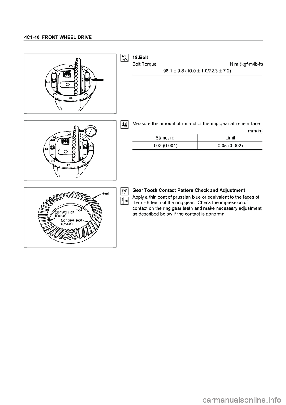
18. Bolt
Bolt Torque N�
m (kgf�
m/lb�
ft)
98.1 � 9.8 (10.0 � 1.0/72.3 � 7.2)
Measure the amount of run-out of the ring gear at its rear face.
mm(in)
Standard Limit
0.02 (0.001) 0.05 (0.002)
Gear Tooth Contact Pattern Check and Adjustment
Apply a thin coat of prussian blue or equivalent to the faces of
the 7 - 8 teeth of the ring gear. Check the impression of
contact on the ring gear teeth and make necessary adjustment
as described below if the contact is abnormal.
Page 261 of 4264
FRONT WHEEL DRIVE 4C1-41
20. Differential Assembly
(1) Clean the faces of the front axle case and differential
carrier.
Apply the recommended liquid gasket or its equivalent to
the sealing side of the axle case and the carrier.
(2) Attach the differential case and the carrier assembly to the
front axle case and tighten the nuts and bolts. The axle
case bolt is used for drainage.
Torque N�
m (kgf�
m/lb�
ft)
26 �
5 (2.6 �
0.5/18.8 �
3.6)
(3) Install the axle shaft assemblies as instructed earlier in this
section under “Axle Shaft Replacement”.
(4) Fill the axle case with hypoid gear lubricant, to just belo
w
the filler hole.
Lubricant capacity liter (US/UK gal)
1.4 (0.37/0.31)
Page 267 of 4264
FRONT WHEEL DRIVE 4C1-47
Important Operations
1. Wheel Pin
(1) Place hub on a wood workbench or a block of wood,
approx. 6” by 6” to protect the wheel stud ends and threads.
(2) Install wheel stud using a hammer.
Be sure wheel stud is started squarely and seats
completely.
(3) Align index marks and install hub to disc.
2. Bolt
Torque N�
m (kgf�
m/lb�
ft)
103 �
10 (10.5 �
1/75.9 �
7.2)
3. ABS sensor rotor
(1) Set a new ABS sensor rotor, if replacement is required.
(2) Install the ABS sensor rotor in the hub, using special tools.
Installer : 5-8840-2789-0
Grip : 5-8840-0007-0
Refer to the section Brake.
4. Inner Bearing and Outer Race
5. Oil Seal
�
Outer Bearing Outer Race
(1) Install the bearing outer race by driving into the hub.
Installer (Outer) : 5-8822-0053-0 (J-29016)
Installer (Inner) : 5-8822-0054-0 (J-29015)
Drive handle : 5-8840-0007-0 (J-8092)
Page 268 of 4264
 Install the outer and inner bearing into the hub with fingers.
(3) Install oil seal using special tools.
Discard the used oil seal and install a new one.")
4C1-48 FRONT WHEEL DRIVE
(2) Install the outer and inner bearing into the hub with fingers.
(3) Install oil seal using special tools.
Discard the used oil seal and install a new one.
Installer : 5-8522-0051-0
(J-33161)
Grip : 5-8840-0007-0
(J-8092)
Hub cap Hub
6. Hub and Disc Assembly
12. Hub Cap
Apply grease in the hub and hub cap.
Description Amount g(oz)
Hub 50 (1.76)
Hub cap 20 (0.70)
Outer bearing 6.5 (0.23)
Inner bearing 12 (0.42)
9. Hub nut
Adjustment of front wheel hub bearing preload
1. Tighten spindle nut to 3.0 kg�m (21.7 lb.ft/29.4 N�m) torque.
2. Turn the hub 2-3 turns and loosen the nut just enough so
that it can be turned with the fingers.
3. Turn the nut all the way in with the fingers and check to be
sure the hub has no free play.
4. Measure the bearing preload by pulling one of the wheel
hub studs with a spring scale.
5. Tighten the spindle nut until specified bearing preload Is
obtained.
6. Install the split pin in the nut retainer.
Discard the used split pin and install a new one.
After reassembling, install the disc brake caliper assembly.
Bearing Preload N�
m (kgf�
m/lb�
ft)
New bearing and New oil seal 8-12 (0.8-1.2 / 69-104)
Reuse bearing and New oil seal 8-12 (0.8-1.2 / 69-104)
Page 269 of 4264
FRONT WHEEL DRIVE 4C1-49
14.Bolt
Torque N�m (kgf�m/lb�ft)
215.7 �
19.6 (22 �
2/159.2 �
14.5)
 Be sure to install the cross pin so that it is in alignment with
the lock pin hole in the differential cage.
(2)
Adjust the backlash between")
 Clean the faces of the front axle case and differential
carrier.
Apply the recommended liquid gasket or its")
 Place hub on a wood workbench or a block of wood,
approx. 6” by 6” to protect the wheel stud ends and threads.
(2) Install whee")
