Page 3428 of 4264
3A-12 FRONT ALIGNMENT
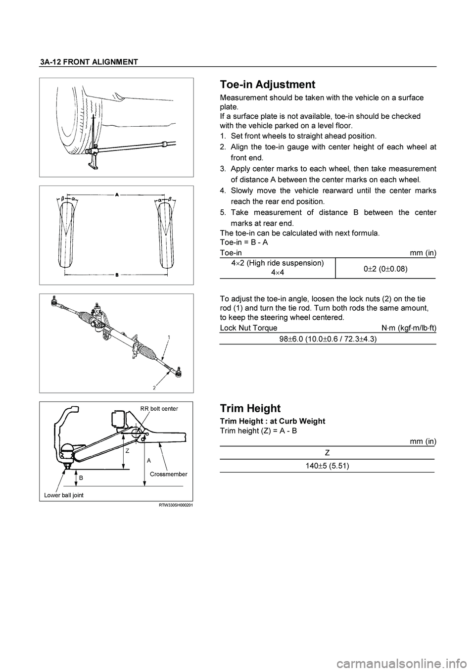
Toe-in Adjustment
Measurement should be taken with the vehicle on a surface
plate.
If a surface plate is not available, toe-in should be checked
with the vehicle parked on a level floor.
1. Set front wheels to straight ahead position.
2. Align the toe-in gauge with center height of each wheel a
t
front end.
3.
Apply center marks to each wheel, then take measurement
of distance A between the center marks on each wheel.
4. Slowly move the vehicle rearward until the center marks
reach the rear end position.
5. Take measurement of distance B between the cente
r
marks at rear end.
The toe-in can be calculated with next formula.
Toe-in = B - A
Toe-in mm (in)
4�2 (High ride suspension)
4�4 0�2 (0�0.08)
To adjust the toe-in angle, loosen the lock nuts (2) on the tie
rod (1) and turn the tie rod. Turn both rods the same amount,
to keep the steering wheel centered.
Lock Nut Torque N�
m (kgf�
m/lb�
ft)
98�6.0 (10.0�0.6 / 72.3�4.3)
RTW330SH000201
Trim Height
Trim Height : at Curb Weight
Trim height (Z) = A - B
mm (in)
Z
140�
5 (5.51)
Page 3431 of 4264
POWER-ASSISTED STEERING SYSTEM 3B-1
STEERING
POWER-ASSISTED STEERING SYSTEM
TABLE OF CONTENTS
PAGE
General Description ......................................................................................................... 3B – 4
Power Steering System Test ........................................................................................... 3B – 7
Maintenance ..................................................................................................................... 3B – 8
Fluid Level ........................................................................................................................ 3B – 8
Bleeding The Power Steering System............................................................................ 3B – 8
Bleeding Procedure ......................................................................................................... 3B – 8
Flushing The Power Steering System ............................................................................ 3B – 8
Steering Wheel Free Play Inspection ............................................................................. 3B – 9
Front End Alignment Inspection and Adjustment ......................................................... 3B – 9
Special Tools .................................................................................................................... 3B – 10
Power Steering Unit ......................................................................................................... 3B – 11
Power Steering Unit and Associated Parts ............................................................... 3B – 11
Removal ....................................................................................................................... 3B – 11
Installation ................................................................................................................... 3B – 12
Power Steering Unit Disassembled View .................................................................. 3B – 13
Disassembly ................................................................................................................ 3B – 13
Inspection and Repair ................................................................................................. 3B – 13
Reassembly ................................................................................................................. 3B – 14
Main Data and Specifications ..................................................................................... 3B – 14
Special Tools ............................................................................................................... 3B – 15
Power Steering Pump and Associated Parts (4JH1-TC, 4JA1-TC, 4JA1-L) ............ 3B – 16
Removal ....................................................................................................................... 3B – 16
Installation ................................................................................................................... 3B – 16
Power Steering Pump Disassembled View .............................................................. 3B – 17
Disassembly ................................................................................................................ 3B – 18
Inspection and Repair ................................................................................................. 3B – 18
Reassembly ................................................................................................................. 3B – 19
Main Data and Specifications ..................................................................................... 3B – 19
Page 3439 of 4264
POWER-ASSISTED STEERING SYSTEM 3B-9
4. Install all the lines and hoses. Fill the system with
new power steering fluid and bleed the system as
described in Bleeding The Power Steering System.
Operate the engine for about 15 minutes.
Remove the pump return line at the pump inlet and
plug the connection on the pump. While refilling the
reservoir, check the draining fluid for contamination.
If foreign material is still evident, replace all lines,
disassemble and clean or replace the powe
r
steering system components. Do not re-use any
drained power steering fluid.
Steering Wheel Free Play Inspection
060R300016
1. With the tires in the straight-ahead position, check
the amount of steering wheel play by turning the
wheel in both directions until the tires begin to move.
NOTE: The wheel free play should be checked with the
engine running.
Free play: 0 - 30 mm (0 - 1.18 in)
2.
Also check the steering wheel for play and
looseness in the mount by moving it back and forth
and sideways. When test driving, check for hard
steering, steering shimmy and tendency to pull to
one side.
Front End Alignment Inspection and
Adjustment
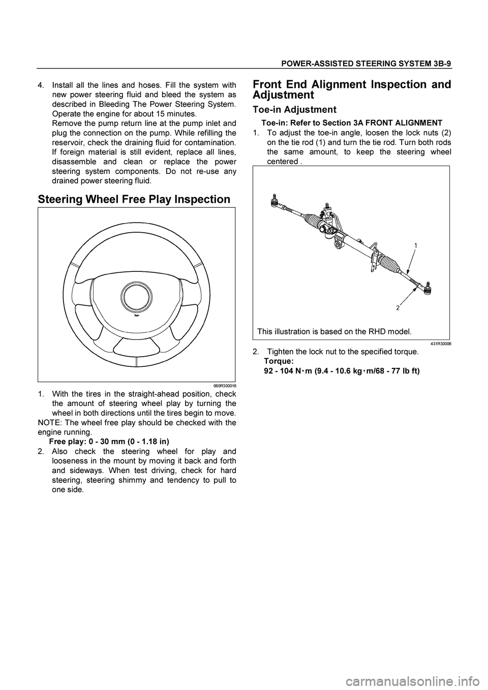
Toe-in Adjustment
Toe-in: Refer to Section 3A FRONT ALIGNMENT
1. To adjust the toe-in angle, loosen the lock nuts (2)
on the tie rod (1) and turn the tie rod. Turn both rods
the same amount, to keep the steering wheel
centered .
This illustration is based on the RHD model.
431R30006
2. Tighten the lock nut to the specified torque.
Torque:
92 - 104 N�
�� �m (9.4 - 10.6 kg�
�� �m/68 - 77 lb ft)
Page 3503 of 4264
FRONT SUSPENSION 3C-11
NOTE: Paint mark to be outer side of after assembly to
vehicle.
2. Install nut (2), then tighten it to the specified
torque.
Torque: 55N
�
�� �m (5.6kg
�
�� �m/41lb ft)
3. Install bolt (7) and nut (4), then tighten to the
specified torque.
Buffer clearance: 25.9 mm (1.02 in)
Torque: 137N�
�� �m (14.0kg�
�� �m/101 lb ft)
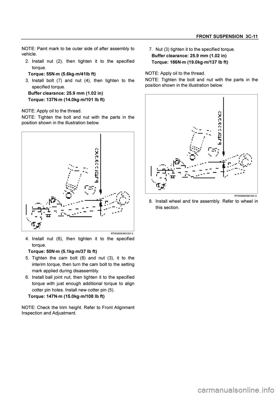
NOTE: Apply oil to the thread.
NOTE: Tighten the bolt and nut with the parts in the
position shown in the illustration below.
RTW340SH001301-X
4. Install nut (6), then tighten it to the specified
torque.
Torque: 50N�
�� �m (5.1kg�
�� �m/37 lb ft)
5. Tighten the cam bolt (8) and nut (3), it to the
interim torque, then turn the cam bolt to the setting
mark applied during disassembly.
6. Install ball joint nut, then tighten it to the specified
torque with just enough additional torque to align
cotter pin holes. Install new cotter pin (5).
Torque: 147N�
�� �m (15.0kg�
�� �m/108 lb ft)
NOTE: Check the trim height. Refer to Front Alignment
Inspection and Adjustment.
7. Nut (3) tighten it to the specified torque.
Buffer clearance: 25.9 mm (1.02 in)
Torque: 186N�
�� �m (19.0kg�
�� �m/137 lb ft)
NOTE: Apply oil to the thread.
NOTE: Tighten the bolt and nut with the parts in the
position shown in the illustration below.
RTW340SH001301-X
8. Install wheel and tire assembly. Refer to wheel in
this section.
Page 3546 of 4264
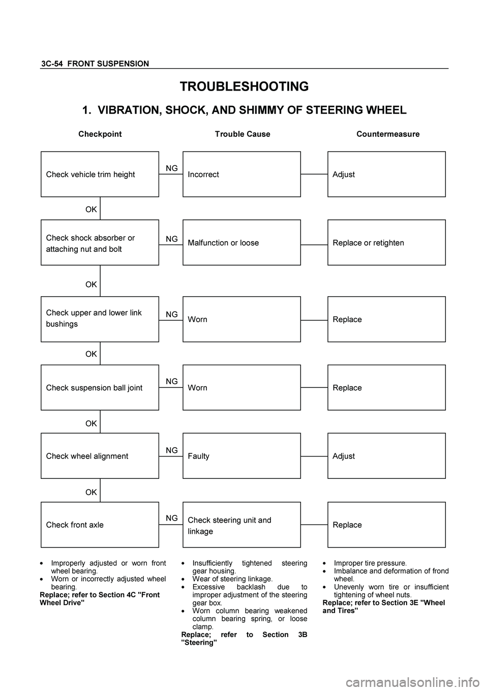
3C-54 FRONT SUSPENSION
TROUBLESHOOTING
1. VIBRATION, SHOCK, AND SHIMMY OF STEERING WHEEL
Checkpoint Trouble Cause Countermeasure
Check front axle
Check wheel alignment
Check suspension ball joint
Check shock absorber or
attaching nut and bolt
Replace
Adjust
Replace
Replace or retighten
Check steering unit and
linkage
Faulty
Worn
Malfunction or loose
Check upper and lower link
bushings
Replace
Adjust
Worn
Incorrect
OK OK OK
NG NG NG NG NG NG
OK OK
Check vehicle trim height
�
Improperly adjusted or worn front
wheel bearing.
�
Worn or incorrectl
y adjusted wheel
bearing.
Replace; refer to Section 4C "Front
Wheel Drive"
�
Insufficientl
y tightened steeringgear housing.
�
Wear of steering linkage.
�
Excessive backlash due to
improper ad
justment of the steeringgear box.
� Worn column bearing weakened
column bearing spring, or loose
clamp.
Replace; refer to Section 3B
"Steering"
�
Improper tire pressure.
� Imbalance and deformation of frond
wheel.
�
Unevenl
y worn tire or insufficient
tightening of wheel nuts.
Replace; refer to Section 3E "Wheel
and Tires"
Page 3547 of 4264
FRONT SUSPENSION 3C-55
2. VEHICLE PULLS TO RIGHT OR LEFT
Checkpoint Trouble Cause Countermeasure
Steering linkage, and upper
and lower link
Rubber bushing for upper and
lower link
Wheel alignment
Vehicle trim height
Replace
Replace
Adjust
Adjust
Deformed
Worn
Incorrect
Incorrect
Brake adjustment (binding)
Adjust
Replace
Incorrect
Collapsed or break (4�
2
Except high ride suspension)
Collapsed or twisted (4�
4, 4�
2
High ride suspension)
Continued on the next pageOK OK OK OK
NG NG NG NG NG NG
OK OK Coil spring (4�2 Except high
ride suspension)
Torsion bar (4�
4, 4�
2 High
ride suspension)
Front wheel bearing
Adjust or replace
Incorrect adjustment or
abrasion
NG
Page 3549 of 4264
FRONT SUSPENSION 3C-57
3. INSTABILITY OF VEHICLE
Checkpoint Trouble Cause Countermeasure
Tire pressure
Wheel alignment
Rubber bushings for upper
and lower links. (4 � 2 Except
high ride suspension)
Adjust
Adjust
Replace
Incorrect
Incorrect
Worn
Steering linkage and upper
and lower links
Replace
Adjust
Worn or deformed
Incorrect
OK OK OK
NG NG NG NG NG
OK OK
Vehicle trim height
Road wheel
Adjust
Deformed or unbalanced
NG
Page 3550 of 4264
3C-58 FRONT SUSPENSION
4. STIFF STEERING WHEEL
Checkpoint Trouble Cause Countermeasure
Steering gear box or steering
linkage
Steering linkage
Steering gear
Wheel alignment
Replace the part
Replace
Replace
Adjust
Insufficient lubricants or
impurities present; or
excessively worn
Deformed
Worn or damaged
Incorrect
Replace
Stiff or damaged or lack of
grease
OK OK OK OK OK
NG NG NG NG NG
OK
Upper and ball joint
Steering column with turn
signal switch
Replace
Interference abrasion
NG
Tire pressure
Adjust
Improper
NG