2004 ISUZU TF SERIES fuel filter
[x] Cancel search: fuel filterPage 1304 of 4264
6C – 4 FUEL SYSTEM
GENERAL DESCRIPTION
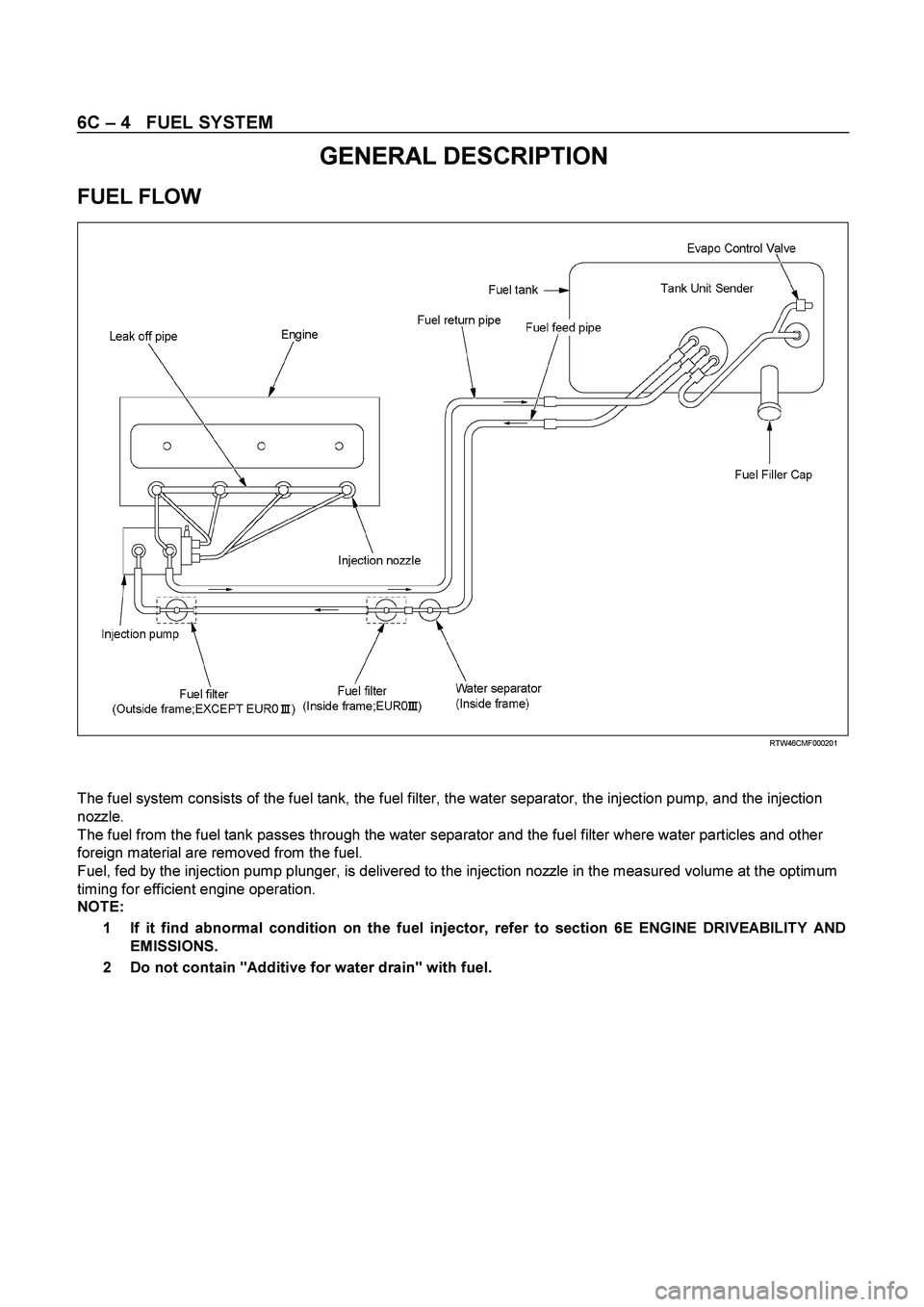
FUEL FLOW
RTW46CM F000201
The fuel system consists of the fuel tank, the fuel filter, the water separator, the injection pump, and the injection
nozzle.
The fuel from the fuel tank passes through the water separator and the fuel filter where water particles and other
foreign material are removed from the fuel.
Fuel, fed by the injection pump plunger, is delivered to the injection nozzle in the measured volume at the optimum
timing for efficient engine operation.
NOTE:
1 If it find abnormal condition on the fuel injector, refer to section 6E ENGINE DRIVEABILITY AND
EMISSIONS.
2 Do not contain "Additive for water drain" with fuel.
Page 1305 of 4264
FUEL SYSTEM 6C – 5
FUEL FILTER AND WATER SEPARATOR
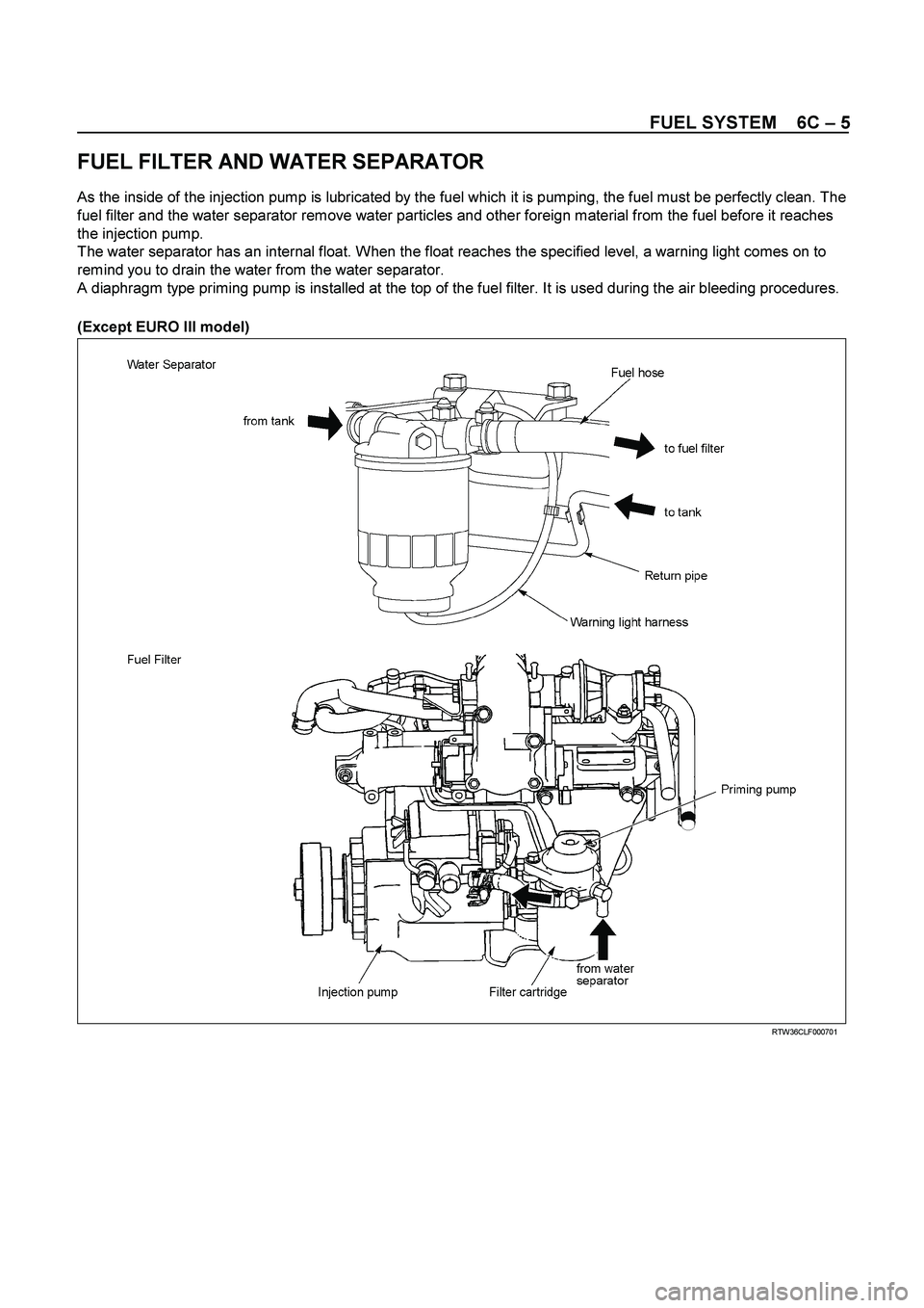
As the inside of the injection pump is lubricated by the fuel which it is pumping, the fuel must be perfectly clean. The
fuel filter and the water separator remove water particles and other foreign material from the fuel before it reaches
the injection pump.
The water separator has an internal float. When the float reaches the specified level, a warning light comes on to
remind you to drain the water from the water separator.
A diaphragm type priming pump is installed at the top of the fuel filter. It is used during the air bleeding procedures.
(Except EURO III model)
RTW36CLF000701
Page 1320 of 4264
6C – 20 FUEL SYSTEM
7. Power Steering Pump Bracket
6C-4 8. Throttle Position Sensor Harness Connector
(4JA1TC/4JH1TC only)
Disconnect the harness connector from the throttle
position sensor.
9. Oil Level Gauge
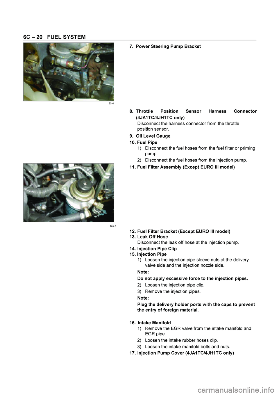
10. Fuel Pipe
1) Disconnect the fuel hoses from the fuel filter or priming
pump.
2) Disconnect the fuel hoses from the injection pump.
11. Fuel Filter Assembly (Except EURO III model)
6C-5
12. Fuel Filter Bracket (Except EURO III model)
13. Leak Off Hose
Disconnect the leak off hose at the injection pump.
14. Injection Pipe Clip
15. Injection Pipe
1) Loosen the injection pipe sleeve nuts at the delivery
valve side and the injection nozzle side.
Note:
Do not apply excessive force to the injection pipes.
2) Loosen the injection pipe clip.
3) Remove the injection pipes.
Note:
Plug the delivery holder ports with the caps to prevent
the entry of foreign material.
16. Intake Manifold
1) Remove the EGR valve from the intake manifold and
EGR pipe.
2) Loosen the intake rubber hoses clip.
3) Loosen the intake manifold bolts and nuts.
17. Injection Pump Cover (4JA1TC/4JH1TC only)
Page 1324 of 4264
6C – 24 FUEL SYSTEM
6. Injection Pipe
Install the injection pipe.
Injection Pipe Torque N·m(kg·m / lb ft)
29 (3.0 / 22)
Nozzle Side (4JA1TC/4JH1TC) N·m(kg·m / lb ft)
29 (3.0 / 22)
Pump Side (4JA1TC/4JH1TC) N·m(kg·m / lb ft)
40 (4.1 / 30)
7. Injection Pipe Clip
Install the injection pipe clip.
Note:
Make absolutely sure that the clip is correctly
positioned.
Injection Pipe Clip Torque N·m(kg·m / lb in)
8 (0.8 / 69)
8. Leak Off Pipe and Leak Off Hose
Install the leak off pipe to injection nozzle and connect the
leak off hose to the injection pump.
9. Fuel Filter Bracket (Except EURO III model)
Install the fuel filter bracket and tighten bolts to the
specified torque.
Fuel Filter Bracket Bolts Torque N·m(kg·m / lb ft)
21 (2.1 / 15)
10. Fuel Filter Assembly (Except EURO III model)
Install the fuel filter assembly to bracket and tighten bolts
to the specified torque.
Fuel Filter Assembly Bolts
Torque N·m(kg·m / lb ft)
21 (2.1 / 15)
11. Fuel Pipe
1) Connect the fuel hoses to the fuel filter or priming
pump.
2) Connect the fuel hoses to the injection pump.
12. Oil Level Gauge
Install the oil level gauge and tighten bolts to the specified
torque.
Oil Level Gauge Bolts
Torque N·m(kg·m / lb ft)
M8: 19 (1.9 / 14)
M6: 8 (0.8/6 lb in)
Page 1384 of 4264
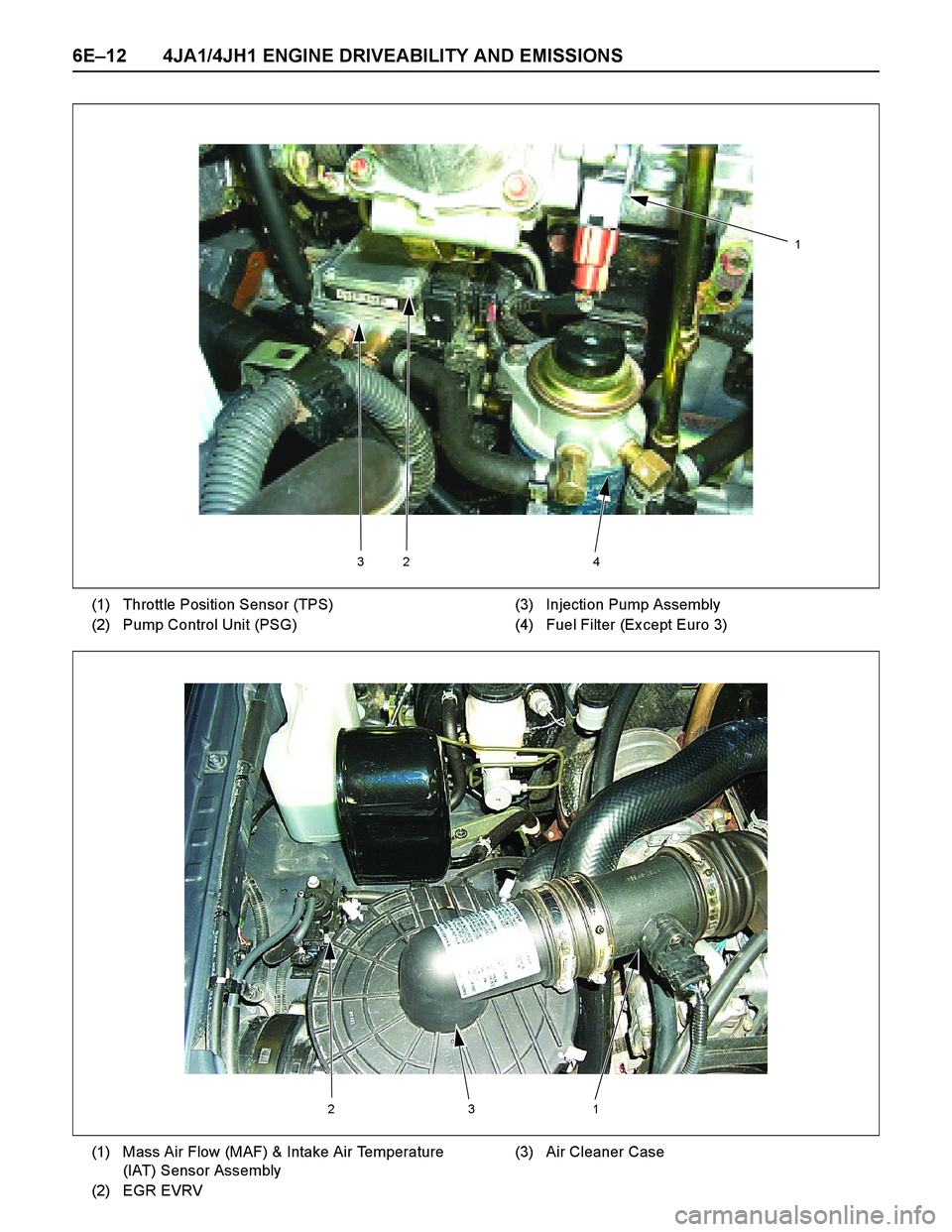
6E–12 4JA1/4JH1 ENGINE DRIVEABILITY AND EMISSIONS
324
1
(1) Throttle Position Sensor (TPS)
(2) Pump Control Unit (PSG)(3) Injection Pump Assembly
(4) Fuel Filter (Ex cept Euro 3)
213
(1) Mass Air Flow (MAF) & Intake Air Temperature
(IAT) Sensor Assembly
(2) EGR EVRV(3) Air Cleaner Case
Page 1454 of 4264
6E–82 4JA1/4JH1 ENGINE DRIVEABILITY AND EMISSIONS
GENERAL SERVICE INFORMATION
Serviceability Issues
Non-OEM Parts
All of the OBD diagnostics have been calibrated to run
with OEM parts. Accordingly, if commercially sold
sensor or switch is installed, it makes a wrong diagnosis
and turns on the check engine lamp.
Aftermarket electronics, such as cellular phones,
stereos, and anti-theft devices, may radiate EMI into the
control system if they are improperly installed. This may
cause a false sensor reading and turn on the check
engine lamp.
Poor Vehicle Maintenance
The sensitivity of OBD diagnostics will cause the check
engine lamp to turn on if the vehicle is not maintained
properly. Restricted oil filters, fuel filters, and crankcase
deposits due to lack of oil changes or improper oil
viscosity can trigger actual vehicle faults that were not
previously monitored prior to OBD. Poor vehicle
maintenance can not be classified as a “non-vehicle
fault”, but with the sensitivity of OBD diagnostics,
vehicle maintenance schedules must be more closely
followed.
Related System Faults
Many of the OBD system diagnostics will not run if the
ECM detects a fault on a related system or component.
Visual/Physical Engine Compartment
Inspection
Perform a careful visual and physical engine
compartment inspection when performing any
diagnostic procedure or diagnosing the cause of an
emission test failure. This can often lead to repairing a
problem without further steps. Use the following
guidelines when performing a visual/physical
inspection:
Inspect all vacuum hoses for punches, cuts,
disconnects, and correct routing.
Inspect hoses that are difficult to see behind other
components.
Inspect all wires in the engine compartment for
proper connections, burned or chafed spots, pinched
wires, contact with sharp edges or contact with hot
exhaust manifolds or pipes.
Basic Knowledge of Tools Required
NOTE: Lack of basic knowledge of this powertrain
when performing diagnostic procedures could result in
an incorrect diagnosis or damage to powertrain
components. Do not attempt to diagnose a powertrain
problem without this basic knowledge.
A basic understanding of hand tools is necessary to
effectively use this section of the Service Manual.
ON-BOARD DIAGNOSTIC (OBD)
On-Board Diagnostic (Self Diagnosis
System) Tests
A diagnostic test is a series of steps, the result of which
is a pass or fail reported to the diagnostic ex ecutive.
When a diagnostic test reports a pass result, the
diagnostic ex ecutive records the following data:
The diagnostic test has been completed since the
last ignition cycle.
The diagnostic test has passed during the current
ignition cycle.
The fault identified by the diagnostic test is not
currently active.
When a diagnostic test reports a fail result, the
diagnostic ex ecutive records the following data:
The diagnostic test has been completed since the
last ignition cycle.
The fault identified by the diagnostic test is currently
active.
The fault has been active during this ignition cycle.
The operating conditions at the time of the failure.
The Diagnostic Executive
The Diagnostic Executive is a unique segment of
software which is designed to coordinate and prioritize
the diagnostic procedures as well as define the protocol
for recording and displaying their results. The main
responsibilities of the Diagnostic Ex ecutive are listed as
follow s:
Commanding the check engine lamp on and off
DTC logging and clearing
Current status information on each diagnostic
Diagnostic Information
The diagnostic charts and functional checks are
designed to locate a faulty circuit or component through
a process of logical decisions. The charts are prepared
with the requirement that the vehicle functioned
correctly at the time of assembly and that there are not
multiple faults present.
There is a continuous self-diagnosis on certain control
functions. This diagnostic capability is complemented
by the diagnostic procedures contained in this manual.
The language of communicating the source of the
malfunction is a system of diagnostic trouble codes.
When a malfunction is detected by the control module, a
diagnostic trouble code is set and the check engine
lamp is illuminated.
Check Engine Lamp
The check engine lamp looks the same as the check
engine lamp you are already familiar with, the “Check
Engine” lamp.
Basically, the check engine lamp is turned on when the
Page 1488 of 4264
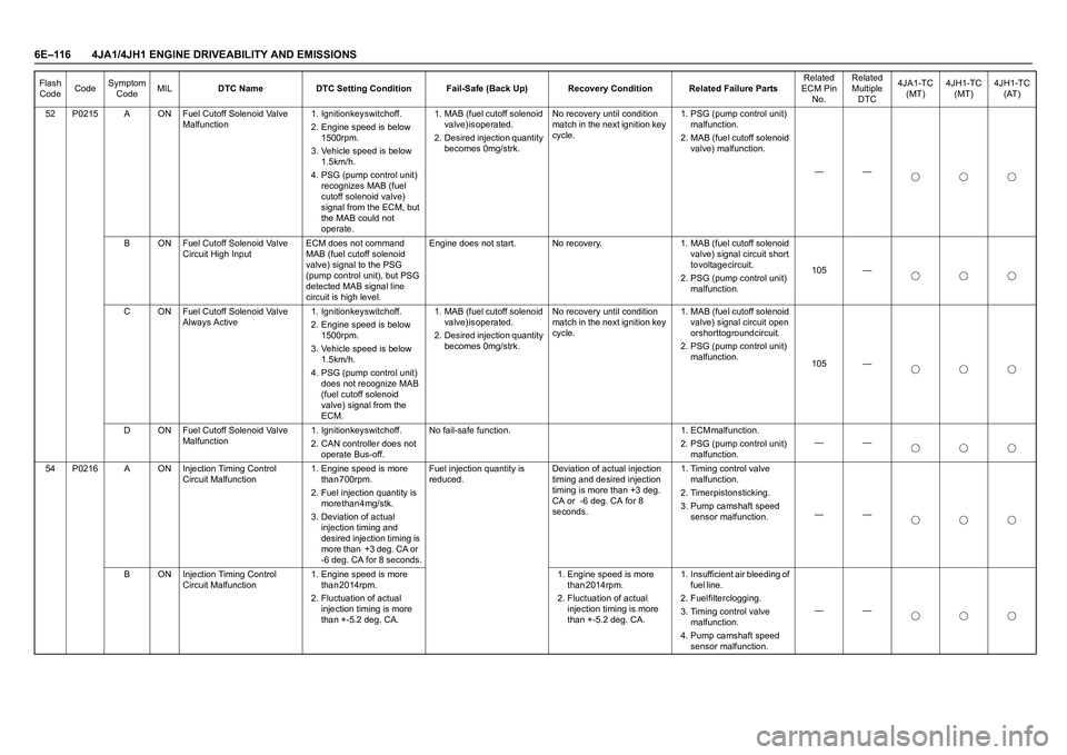
6E–116 4JA1/4JH1 ENGINE DRIVEABILITY AND EMISSIONS
52 P0215 A ON Fuel Cutoff Solenoid Valve
Malfunction1. Ignition key switch off.
2. Engine speed is below
1 5 0 0 r p m .
3. Vehicle speed is below
1 . 5 k m / h .
4. PSG (pump control unit)
recognizes MAB (fuel
cutoff solenoid valve)
signal from the ECM, but
the MAB could not
operate. 1. MAB (fuel cutoff solenoid
v a l v e ) i s o p e r a t e d .
2. Desired injection quantity
becomes 0mg/strk.No recovery until condition
match in the next ignition key
cycle.1. PSG (pump control unit)
m a l f u n c t i o n .
2. MAB (fuel cutoff solenoid
valve) malfunction.
——
B ON Fuel Cutoff Solenoid Valve
Circuit High InputECM does not command
MAB (fuel cutoff solenoid
valve) signal to the PSG
(pump control unit), but PSG
detected MAB signal line
circuit is high level.Engine does not start. No recovery. 1. MAB (fuel cutoff solenoid
valve) signal circuit short
t o v o l t a g e c i r c u i t .
2. PSG (pump control unit)
malfunction.105 —
C ON Fuel Cutoff Solenoid Valve
Always Active1. Ignition key switch off.
2. Engine speed is below
1 5 0 0 r p m .
3. Vehicle speed is below
1 . 5 k m / h .
4. PSG (pump control unit)
does not recognize MAB
(fuel cutoff solenoid
valve) signal from the
ECM. 1. MAB (fuel cutoff solenoid
v a l v e ) i s o p e r a t e d .
2. Desired injection quantity
becomes 0mg/strk.No recovery until condition
match in the next ignition key
cycle.1. MAB (fuel cutoff solenoid
valve) signal circuit open
or short to ground circuit.
2. PSG (pump control unit)
malfunction.
105 —
D ON Fuel Cutoff Solenoid Valve
Malfunction1. Ignition key switch off.
2. CAN controller does not
operate Bus-off.N o f a i l - s a f e f u n c t i o n . 1 . E C M m a l f u n c t i o n .
2. PSG (pump control unit)
malfunction.——
54 P0216 A ON Injection Timing Control
Circuit Malfunction1. Engine speed is more
t h a n 7 0 0 r p m .
2. Fuel injection quantity is
more than 4mg/stk.
3. Deviation of actual
injection timing and
desired injection timing is
more than +3 deg. CA or
-6 deg. CA for 8 seconds.Fuel injection quantity is
reduced.Deviation of actual injection
timing and desired injection
timing is more than +3 deg.
CA or -6 deg. CA for 8
seconds.1. Timing control valve
m a l f u n c t i o n .
2 . T i m e r p i s t o n s t i c k i n g .
3. Pump camshaft speed
sensor malfunction.——
B ON Injection Timing Control
Circuit Malfunction 1. Engine speed is more
t h a n 2 0 1 4 r p m .
2. Fluctuation of actual
injection timing is more
than +-5.2 deg. CA.1. Engine speed is more
than 2014rpm.
2. Fluctuation of actual
injection timing is more
than +-5.2 deg. CA.1. Insufficient air bleeding of
f u e l l i n e .
2. Fuel filter clogging.
3. Timing control valve
m a l f u n c t i o n .
4. Pump camshaft speed
sensor malfunction. —— Flash
CodeCodeSymptom
CodeMILDTC Name DTC Setting Condition Fail-Safe (Back Up) Recovery Condition Related Failure PartsRelated
ECM Pin
No.Related
Multiple
DTC4JA1-TC
(MT)4JH1-TC
(MT)4JH1-TC
(AT)
Page 1551 of 4264
4JA1/4JH1 ENGINE DRIVEABILITY AND EMISSIONS 6E–179
Circuit Description
The ECM is calculates an injection quantity and an
injection timing using the various sensors (crankshaft
position sensor, camshaft position sensor, engine
coolant temperature sensor, etc.). The timing control
valve (TCV) operation performs an injection timing
decision.
The TCV performs as a variable throttle, using the rapid
opening and closing cycle of the valve needle in the
TCV.
The TCV is assembled in the injection pump. The signal
of desired injection timing and actual injection timing are
ex changed via the CAN-bus between the PSG and
ECM.
If the timer position is out of tolerance (deviation or
fluctuation), DTC P0216 will be stored.
Diagnostic Aids
An intermittent may be caused by the following:
Poor connections.
Misrouted harness.
Rubbed through wire insulation.
Broken wire inside the insulation.
Insufficient air bleeding of fuel line.
Low fuel quantity in the fuel tank.
Check for the following conditions:
Insufficient air bleeding of fuel line inside, clogged
fuel filter or pinched fuel pipe/hose may cause the
DTC store or improper engine performance.Air bleeding procedure:
1.Operate the priming pump until strong resistance is
felt.
2.Wait 1 minute, and operate the priming pump until
strong resistance is felt.
3.Wait 1 minute, and operate the priming pump until
strong resistance is felt.
4.Turn the ignition switch to the "ON" position. Wait
until the glow indicator lamp turns off.
5.Turn the ignition switch to the "START" position and
crank the engine until it starts.
6.If the engine does not start, repeat Step 3 - 5.
7.Allow the engine to idle for 3 minutes to bleed air
completely form the fuel system and check for fuel
leakage.
Poor connection at ECM and PSG-Inspect harness
connectors for backed out terminals, improper
mating, broken locks, improperly formed or damaged
terminals, and poor terminal to wire connection.
Damaged harness-Inspect the wiring harness for
damage. If the harness appears to be OK, observe
the "Actual Injection Start" display on the Tech2 while
moving connectors and wiring harness related to the
sensor.