Page 1241 of 4264
ENGINE MECHANICAL 6A – 101
MAJOR COMPONENT
Reassembly Steps-1
1.
Cylinder body 10.
Camshaft timing gear
2.
Tappet 11. Piston and connecting rod with
upper bearing
3.
Crankshaft upper bearing 12. Connecting rod bearing cap with
lower bearing
4.
Crankshaft 13.
Piston cooling oil pipe
5.
Crankshaft thrust bearing 14.
Oil pump with oil pipe
6. Crankshaft bearing cap with
lower bearing 15.
Crankshaft rear oil seal
7.
Camshaft 16.
Crank case
8.
Timing gear case 17.
Cylinder body rear plate
9.
Camshaft thrust plate 18.
Flywheel
014R300004
Page 1248 of 4264

6A – 108 ENGINE MECHANICAL
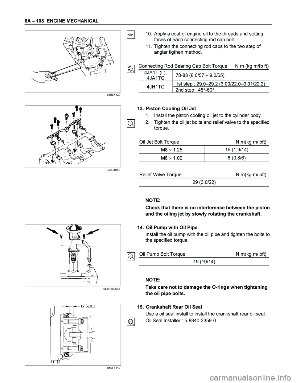
10. Apply a coat of engine oil to the threads and setting
faces of each connecting rod cap bolt.
11. Tighten the connecting rod caps to the two step of
anglar tigthen method.
Connecting Rod Bearing Cap Bolt Torque N·m (kg·m/Ib ft)
4JA1T (L),
4JA1TC 78-88 (8.0/57 – 9.0/65)
1st step ; 29.0–29.2 (3.00/22.0–3.01/22.2)4JH1TC
2nd step ; 45�-60�
13. Piston Cooling Oil Jet
1. Install the piston cooling oil jet to the cylinder body.
2. Tighten the oil jet bolts and relief valve to the specified
torque.
Oil Jet Bolt Torque N·m(kg·m/lbft)
M8 � 1.25 19 (1.9/14)
M6 � 1.00 8 (0.8/6)
Relief Valve Torque N·m(kg·m/lbft)
29 (3.0/22)
NOTE:
Check that there is no interference between the piston
and the oiling jet by slowly rotating the crankshaft.
14. Oil Pump with Oil Pipe
Install the oil pump with the oil pipe and tighten the bolts to
the specified torque.
Oil Pump Bolt Torque N·m(kg·m/lbft)
19 (19/14)
NOTE:
Take care not to damage the O-rings when tightening
the oil pipe bolts.
15. Crankshaft Rear Oil Seal
Use a oil seal install to install the crankshaft rear oil seal.
Oil Seal Installer : 5-8840-2359-0
015LX130
015LX112 052LX010
051R100004
Page 1258 of 4264
6A – 118 ENGINE MECHANICAL
INSTALLATION
EXTERNAL PARTS
RTW36AMF000701
Installation Steps
1.
Exhaust Manifold 18. Engine Mounting Bracket and
2.
Oil Cooler with Oil Filter Foot
3. Generator Bracket 19. Intake Manifold
4. Water Inlet Pipe 20. Power Steering Oil Pump
5.
Generator and Adjusting Plate Bracket
6.
Vacuum Pump Oil Return Hose 21. Fuel Injection Pipe with Clip
7.
Compressor Bracket 22. Fuel Filter Bracket (Except
EURO III)
8. Turbocharger 23. Fuel Filter Assembly (Except
EURO III)
9. Catalytic Converter 24. Oil Level Gauge
10. Heat Protector 25. EGR Valve
11. Cooling Fan Pulley 26-1. EGR Pipe
12. Oil Cooler Water Pipe 26-2. EGR Cooler (EURO III model
only)
13. Fuel Leak Off Pipe 27. Intake Pipe and Throttle Body
(4JA1TC/4JH1TC only)
14. Oil Pressure Warning Switch 28. Clutch Assembly or Flex Plate
15. Starter Motor
16. Injection Pump
17. Injection Pump Cover
Page 1260 of 4264
6A – 120 ENGINE MECHANICAL
4. Water Inlet Pipe
1) Tighten the water inlet pipe bolts to the specified
torque.
Suction Pipe Bolt Torque N·m(kg·m/Ib ft)
19 (1.9/14)
5. Generator and Adjusting Plate
1) Install the generator to the bracket (1).
2) Temporarily tighten the generator bolt (2) and
adjusting plate bolts (3).
The bolts will be finally tightened after installation of
the cooling fan drive belt.
3) Connect the vacuum pump rubber hose (4) to the
vacuum pump (5), and the oil pan (6).
6. Vacuum Pump Oil Return Hose
Connect the vacuum oil pipe (7) to the vacuum pump, and
the cylinder body
052R300001
7. Compressor Bracket
1) Install the compressor bracket to the cylinder head.
2) Tighten the bracket bolts to the specified torque.
Bracket Bolt Torque N·m(kg·m/Ib ft)
M8�1.25
19 (1.9/14)
M10�1.25
40 (4.1/30)
066RY00002 032R300001
042RY00003
Page 1262 of 4264

6A – 122 ENGINE MECHANICAL
RTW46ASH001601
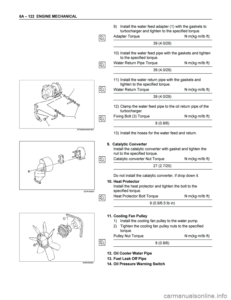
9) Install the water feed adapter (1) with the gaskets to
turbocharger and tighten to the specified torque.
Adapter Torque N·m(kg·m/Ib ft)
39 (4.0/29)
10) Install the water feed pipe with the gaskets and tighten
to the specified torque.
Water Return Pipe Torque N·m(kg·m/Ib ft)
39 (4.0/29)
11) Install the water return pipe with the gaskets and
tighten to the specified torque.
Water Return Torque N·m(kg·m/Ib ft)
39 (4.0/29)
12) Clamp the water feed pipe to the oil return pipe of the
turbocharger.
Fixing Bolt (3) Torque N·m(kg·m/Ib ft)
8 (0.8/6)
13) Install the hoses for the water feed and return.
9. Catalytic Converter
Install the catalytic converter with gasket and tighten the
nut to the specified torque.
Catalytic converter Nut Torque N·m(kg·m/Ib ft)
27 (2.7/20)
Do not install the catalytic converter, if drop down it.
10. Heat Protector
Install the heat protector and tighten the bolt to the
specified torque.
Heat Protector Bolt Torque N·m(kg·m/Ib ft)
9 (0.9/6.5 Ib in)
033R300002
11. Cooling Fan Pulley
1) Install the cooling fan pulley to the water pump.
2) Tighten the cooling fan pulley nuts to the specified
torque.
Pulley Nut Torque N·m(kg·m/Ib ft)
8 (0.8/6)
12. Oil Cooler Water Pipe
13. Fuel Leak Off Pipe
14. Oil Pressure Warning Switch
027R100007
Page 1266 of 4264
6A – 126 ENGINE MECHANICAL
LUBRICATION SYSTEM
LUBRICATING OIL FLOW
1. Oil Pump Relief Valve Operating Pressure: 6.2 - 7.8kg/cm 2 (608 - 764Kpa)
2. Regulating Valve Operating Pressure: 5.7 - 6.3kg/cm 2 (558.6 - 617.4Kpa)
3. Oil Cooler Relief Valve Opening Pressure: 2.8 - 3.4kg/cm 2 (270 - 330Kpa)
4. Oil Filter Relief Valve Opening Pressure: 0.8 - 1.2kg/cm 2 (78.4 - 117.6Kpa)
5. Oil Pressure Switch Operating Pressure: 0.3 - 0.5kg/cm 2 (29.4 - 49.0Kpa)
6. Regulating Valve: 1.8 - 2.2kg/cm 2 (176 - 216Kpa)
The 4J series engine has a full flow type lubricating system.
Lubricating oil is pumped from the oil pump to the cylinder body oil gallery through the oil cooler and the oil filter. It is
then delivered to the vital parts of the engine from the cylinder body oil gallery.
Oiling jets installed on the cylinder body spray engine oil to the piston backside faces to achieve maximum piston
cooling effect.
Page 1267 of 4264
ENGINE MECHANICAL 6A – 127
OIL PUMP AND OIL FILTER
RTW46ALF001501
The 4J series engine is equipped with a gear type oil pump.
The oil filter and the water cooled oil cooler integrated a single unit to increase the cooling effect.
Page 1281 of 4264

ENGINE COOLING 6B – 1
SECTION 6B
ENGINE COOLING
TABLE OF CONTENTS
PAGE
Main Data and Specifications ....................................................................................... 6B - 3
General Description .................................................................................................. 6B - 4
Coolant Flow .............................................................................................................. 6B - 4
Water Pump................................................................................................................ 6B - 5
Thermostat ................................................................................................................. 6B - 5
Radiator ...................................................................................................................... 6B - 6
Diagnosis........................................................................................................................ 6B - 7
Draining and Refilling Cooling System ........................................................................ 6B - 8
Water Pump .................................................................................................................... 6B - 10
Removal and Installation .......................................................................................... 6B - 10
Removal...................................................................................................................... 6B - 10
Inspection and Repair ............................................................................................... 6B - 11
Installation.................................................................................................................. 6B - 11
Thermostat ..................................................................................................................... 6B - 13
Removal and Installation .......................................................................................... 6B - 13
Removal...................................................................................................................... 6B - 13
Inspection and Repair ............................................................................................... 6B - 13
Installation.................................................................................................................. 6B - 14
Radiator .......................................................................................................................... 6B - 15
Removal and Installation .......................................................................................... 6B - 15
Radiator and Associated Parts................................................................................. 6B - 15
Removal...................................................................................................................... 6B - 16
Inspection and Repair ............................................................................................... 6B - 17
Installation.................................................................................................................. 6B - 18