Page 4151 of 4264

DIAGNOSIS (JR405E) 7A2-159
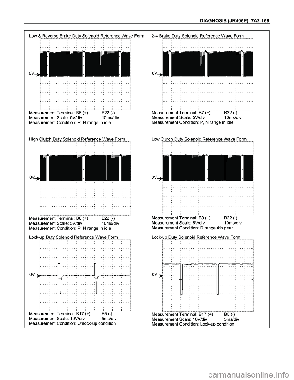
Low & Reverse Brake Duty Solenoid Reference Wave Form
Measurement Terminal: B6 (+) B22 (-)
Measurement Scale: 5V/div 10ms/div
Measurement Condition: P, N range in idle
0V2-4 Brake Duty Solenoid Reference Wave Form
Measurement Terminal: B7 (+) B22 (-)
Measurement Scale: 5V/div 10ms/div
Measurement Condition: P, N range in idle
0V
High Clutch Duty Solenoid Reference Wave Form
Measurement Terminal: B8 (+) B22 (-)
Measurement Scale: 5V/div 10ms/div
Measurement Condition: P, N range in idle
0VLow Clutch Duty Solenoid Reference Wave Form
Measurement Terminal: B9 (+) B22 (-)
Measurement Scale: 5V/div 10ms/div
Measurement Condition: D range 4th gear
0V
Lock-up Duty Solenoid Reference Wave Form
Measurement Terminal: B17 (+) B5 (-)
Measurement Scale: 10V/div 5ms/div
Measurement Condition: Unlock-up condition
0VLock-up Duty Solenoid Reference Wave Form
Measurement Terminal: B17 (+) B5 (-)
Measurement Scale: 10V/div 5ms/div
Measurement Condition: Lock-up condition
0V
Page 4156 of 4264
7A3-4 ON-VEHICLE SERVICE (JR405E)
TRANSMISSION CONTROL MODULE (TCM)
RTW37ALF001901
Remove and Disconnect
1. Disconnect the negative battery cable.
2. Remove the connectors.
3. Remove the fixing nuts and remove the TCM (1)
from the bracket.
Note:
The TCM is fitted under instrument panel of the driver’s
compartment by means of three stud bolts.
Install or Connect
Follow the removal steps in the reverse order. Be
absolutely sure that the connectors are securely
fastened.
AT CONT
Page 4168 of 4264
7A3-16 ON-VEHICLE SERVICE (JR405E)
SOLENOIDS, OIL PRESSURE SWITCH AND OIL TEMPERATURE
SENSOR
244L300003
Legend
1. High clutch oil pressure switch connector
(wire color: Gray)
2. 2-4 brake oil pressure switch connector
(wire color: Brown)
3. Low and reverse brake oil pressure switch connector
(wire color: White)
4. Low and reverse brake duty solenoid connector
(wire color: Pink and White)
5. High clutch duty solenoid connector
(wire color: Green and Gray)
6. Lock-up duty solenoid connector
(wire color: Yellow and Black)
7. 2-4 brake duty solenoid connector
(wire color: Blue and Brown)
8. Low clutch duty solenoid connector
(wire color: Orange and Black)
9. Line pressure solenoid connector
(wire color: Pink)
Page 4175 of 4264

UNIT REPAIR (JR405E) 7A4-1
SECTION 7A4
UNIT REPAIR (JR405E)
TABLE OF CONTENTS
PAGE
Automatic Transmission Disassembly ..................................................................... 7A4 - 2
Control Valve Assembly ............................................................................................ 7A4 - 11
Control Valve Upper Body ........................................................................................ 7A4 - 18
Control Valve Lower Body ........................................................................................ 7A4 - 23
Oil Pump Assembly ................................................................................................... 7A4 - 28
Clutch Pack (Reverse and High Clutch Assembly) ................................................. 7A4 - 33
Carrier and Low Clutch Assembly ........................................................................... 7A4 - 41
Transmission Case .................................................................................................... 7A4 - 54
Bearing and Bearing Race Installation Position ..................................................... 7A4 - 66
Automatic Transmission Reassembly ..................................................................... 7A4 - 69
Service Standard ....................................................................................................... 7A4 - 83
Special Service Tool .................................................................................................. 7A4 - 85
Page 4180 of 4264
7A4-6 UNIT REPAIR (JR405E)
10ASSY116
6. Converter housing
� Position the automatic transmission so that the
converter housing is facing up.
� Remove the 8 bolts and the converter housing.
11ASSY068
7. O-ring
Remove the O-ring from the input shaft.
12ASSY067
8. Oil pump assembly and bearing race
� Remove the 8 bolts.
� Use a slide hammer to remove the oil pump assembly
from the transmission case.
NOTE:
To prevent damage to the oil pump bolt hole threads,
hand-tighten the slide hammer as far as possible.
� Remove the bearing race from the oil pump assembly.
� Inspect the bearing race surfaces for damage.
14ASSY057
9. Input shaft
Pull the input shaft free.
15ASSY049
10.Clutch pack (Reverse and high clutch assembly) and
bearing
� Pull the clutch pack free.
� Remove the bearing from the clutch pack.
Page 4182 of 4264
7A4-8 UNIT REPAIR (JR405E)
25ASSY019
�
Remove the 2-4 brake retainer and return spring.
26ASSY026
14.Carrier assembly (Carrier and low clutch assembly),
bearing, bearing race, and 2 – 4 brake assembly
� Pull the carrier assembly, the bearing, the bearing race
and the 2-4 brake assembly (Dish plate, retaining plate,
drive plate, and driven plate) from the transmission case
at the same time.
� Remove the bearing, the bearing race, and the 2-4
brake assembly from the carrier assembly.
27U-SPG02
�
Remove the 3 brake springs from the transmission case.
28L&R06
15.Low and reverse brake
� Remove the snap ring.
� Pull the low and reverse brake free.
16.Rear extension (2WD) or Adapter case (4WD)
� Rotate the transmission case so that the oil pan opening
is facing up.
� Remove the 10 bolts and the rear extension (2WD) o
r
the adapter case (4WD).
Page 4184 of 4264
7A4-10 UNIT REPAIR (JR405E)
39ASSY006
�
Remove the bearing and the low one-way clutch inner
race from the transmission case.
� Remove the bearing from the low one-way clutch inne
r
race.
40ASSY005
21.Low and reverse brake return spring
Remove the low and reverse brake return spring from the
transmission case.
41L&R02
22.Low and reverse brake piston
� Force compressed air (329kPa/4.0kg/cm
2) through the
transmission case oil passages.
42ASSY004
�
Remove the low and reverse brake piston from the
transmission case.
Page 4189 of 4264
UNIT REPAIR (JR405E) 7A4-15
244L300003
Legend
1. High clutch oil pressure switch connector
(wire color: Gray)
2. 2-4 brake oil pressure switch connector
(wire color: Brown)
3. Low and reverse brake oil pressure
switch connector (wire color: White)
4. Low and reverse brake duty solenoid
connector (wire color: Pink and White)
5. High clutch duty solenoid connector
(wire color: Green and Gray)
6. Lock-up duty solenoid connector (wire
color: Yellow and Black)
7. 2-4 brake duty solenoid connector (wire
color: Blue and Brown)
8. Low clutch duty solenoid connector (wire
color: Orange and Black)
9. Line pressure solenoid connector (wire
color: Pink)