Page 3469 of 4264

060R30")
POWER-ASSISTED STEERING SYSTEM 3B-39
11. Disconnect the SRS air bag connector and horn
lead connector located behind the air bag assembl
y
and remove the air bag assembly. (with SRS air
bag)
060R300041
12. Remove the horn pad and the horn leads at the
center of the wheel (without SRS air bag).
NOTE: It removes previously from the spoke bottom.
RTW33BSH000401
WARNING: THE INFLATOR MODULE SHOULD
ALWAYS BE CARRIED WITH THE COVER AWAY
FROM YOUR BODY AND SHOULD ALWAYS BE
LAID ON A FLAT SURFACE WITH THE COVER SIDE
UP. THIS IS NECESSARY BECAUSE A FREE SPACE
IS PROVIDED TO ALLOW THE AIR CUSHION TO
EXPAND IN THE UNLIKELY EVENT OF
ACCIDENTAL DEPLOYMENT. OTHERWISE,
PERSONAL INJURY MAY RESULT. (with SRS ai
r
bag)
430R300007
13. Apply a setting mark (1) across the steering wheel
and shaft so parts can be reassembled in thei
r
original position. Move the front wheels to the
straight ahead position, then use steering wheel
remover 5-8521-0016-0 to remove the steering
wheel.
430R300008
CAUTION: Never apply force to the steering wheel in
direction of the shaft by using a hammer or othe
r
impact tools in an attempt to remove the steering
wheel. The steering shaft is designed as an energy
absorbing unit.
Page 3471 of 4264
POWER-ASSISTED STEERING SYSTEM 3B-41
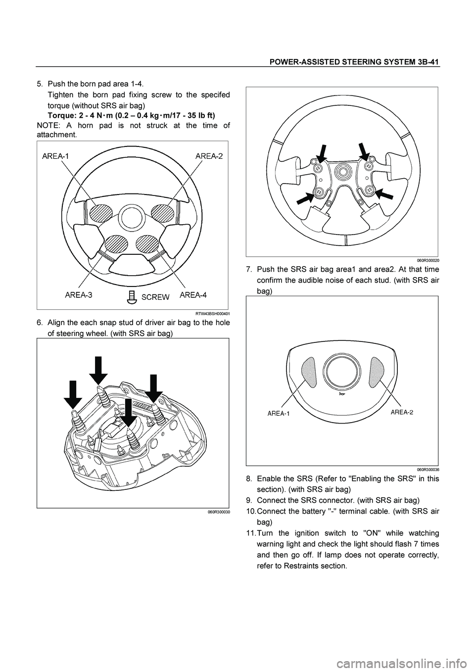
5. Push the born pad area 1-4.
Tighten the born pad fixing screw to the specifed
torque (without SRS air bag)
Torque: 2 - 4 N�
�� �m (0.2 – 0.4 kg�
�� �m/17 - 35 lb ft)
NOTE: A horn pad is not struck at the time o
f
attachment.
RTW43BSH000401
6. Align the each snap stud of driver air bag to the hole
of steering wheel. (with SRS air bag)
060R300030
060R300020
7. Push the SRS air bag area1 and area2. At that time
confirm the audible noise of each stud. (with SRS ai
r
bag)
060R300036
8. Enable the SRS (Refer to "Enabling the SRS" in this
section). (with SRS air bag)
9. Connect the SRS connector. (with SRS air bag)
10. Connect the battery "-" terminal cable. (with SRS ai
r
bag)
11. Turn the ignition switch to "ON" while watching
warning light and check the light should flash 7 times
and then go off. If lamp does not operate correctly,
refer to Restraints section.
Page 3475 of 4264

060R30")
POWER-ASSISTED STEERING SYSTEM 3B-45
13. Disconnect the SRS air bag connector and horn
lead connector located behind the air bag assembl
y
and remove the air bag assembly. (with SRS air
bag)
060R300041
14. Remove the horn pad and the horn leads at the
center of the wheel (without SRS air bag).
NOTE: It removes previously from the spoke bottom.
RTW43BSH00201
WARNING: THE INFLATOR MODULE SHOULD
ALWAYS BE CARRIED WITH THE COVER AWAY
FROM YOUR BODY AND SHOULD ALWAYS BE
LAID ON A FLAT SURFACE WITH THE COVER SIDE
UP. THIS IS NECESSARY BECAUSE A FREE SPACE
IS PROVIDED TO ALLOW THE AIR CUSHION TO
EXPAND IN THE UNLIKELY EVENT OF
ACCIDENTAL DEPLOYMENT. OTHERWISE,
PERSONAL INJURY MAY RESULT. (with SRS ai
r
bag)
430R300007
15. Apply a setting mark (1) across the steering wheel
and shaft so parts can be reassembled in thei
r
original position. Move the front wheels to the
straight ahead position, then use steering wheel
remover 5-8521-0016-0 to remove the steering
wheel.
430R300008
CAUTION: Never apply force to the steering wheel in
direction of the shaft by using a hammer or othe
r
impact tools in an attempt to remove the steering
wheel. The steering shaft is designed as an energy
absorbing unit.
Page 3478 of 4264
3B-48 POWER-ASSISTED STEERING SYSTEM
13. Align the each snap stud of driver air bag to the hole
of steering wheel. (with SRS air bag)
060R300030
060R300020
14. Push the SRS air bag area1 and area2. At that time
confirm the audible noise of each stud. (with SRS ai
r
bag)
060R300036
15. Enable the SRS (Refer to "Enabling the SRS" in this
section). (with SRS air bag)
16. Install driver knee bolster (reinforcement).
17. Install instrument panel lower cover then Install the
engine hood opening lever.
18. Connect the SRS connector. (with SRS air bag)
19. Connect the battery "-" terminal cable. (with SRS ai
r
bag)
20. Turn the ignition switch to "ON" while watching
warning light and check the light should flash 7 times
and then go off. If lamp does not operate correctly,
refer to Restraints section.
Page 3481 of 4264

060R30")
POWER-ASSISTED STEERING SYSTEM 3B-51
13. Disconnect the SRS air bag connector and horn
lead connector located behind the air bag assembl
y
and remove the air bag assembly. (with SRS air
bag)
060R300041
14. Remove the horn pad and the horn leads at the
center of the wheel (without SRS air bag).
NOTE: It removes previously from the spoke bottom.
RTW43BSH00201
15.
Apply a setting mark (1) across the steering wheel
and shaft so parts can be reassembled in thei
r
original position.
430R300008
16. Move the front wheels to the straight ahead position,
then use steering wheel remover 5-8521-0016-0 to
remove the steering wheel.
CAUTION: Never apply force to the steering wheel in
direction of the shaft by using a hammer or othe
r
impact tools in an attempt to remove the steering
wheel. The steering shaft is designed as an energy
absorbing unit.
430RX005-X
WARNING: THE INFLATOR MODULE SHOULD
ALWAYS BE CARRIED WITH THE COVER AWAY
FROM YOUR BODY AND SHOULD ALWAYS BE
LAID ON A FLAT SURFACE WITH THE COVER SIDE
UP. THIS IS NECESSARY BECAUSE A FREE SPACE
IS PROVIDED TO ALLOW THE AIR CUSHION TO
EXPAND IN THE UNLIKELY EVENT OF
ACCIDENTAL DEPLOYMENT. OTHERWISE,
PERSONAL INJURY MAY RESULT. (with SRS ai
r
bag)
Page 3484 of 4264

Torque: 2 - 4 N�
�� �m (0.2 – 0.4 kg�
�� �m/")
3B-54 POWER-ASSISTED STEERING SYSTEM
10. Push the born pad area 1-4.
Tighten the born pad fixing screw to the specifed
torque (without SRS air bag)
Torque: 2 - 4 N�
�� �m (0.2 – 0.4 kg�
�� �m/17 - 35 lb ft)
NOTE: A horn pad is not struck at the time o
f
attachment.
RTW43BSH000401
11. Align the each snap stud of driver air bag to the hole
of steering wheel. (with SRS air bag)
060R300030
060R300020
12. Push the SRS air bag area1 and area2. At that time
confirm the audible noise of each stud. (with SRS ai
r
bag)
060R300036
13. Enable the SRS (Refer to "Enabling the SRS" in this
section). (with SRS air bag)
14. Install driver knee bolster (reinforcement).
15. Install instrument panel lower cover, then install the
engine hood opening lever.
16. Connect the yellow 2-way SRS connector located
under the steering column. (with SRS air bag)
17. Connect the battery "-" terminal cable. (with SRS ai
r
bag)
System Inspection (with SRS air bag)
Turn the ignition switch to "ON" while watching warning
light.
The light should flash 7 times and then go off. If lamp
does not operate correctly, refer to Restraints section.
Page 3491 of 4264
POWER-ASSISTED STEERING SYSTEM 3B-61
System Inspection (with SRS air bag)
Turn the ignition switch to "ON" while watching warning
light.
The light should flash 7 times and then go off. If lamp
does not operate correctly, refer to Restraints section.
Page 3500 of 4264

CONTENTS
Service Precaution............................................. 3C-8
Shock Absorber ................")
3C-8 FRONT SUSPENSION
FRONT SUSPENSION
(4�
�� �2 Except High Ride Suspension)
CONTENTS
Service Precaution............................................. 3C-8
Shock Absorber ................................................. 3C-9
Shock Absorber and Associated Parts ........... 3C-9
Removal ......................................................... 3C-9
Installation....................................................... 3C-10
Shock Absorber with Coil Spring .................... 3C-12
Stabilizer Bar ..................................................... 3C-15
Stabilizer Bar and Associated Parts ............... 3C-15
Removal ......................................................... 3C-15
Inspection and Repair..................................... 3C-15
Installation....................................................... 3C-16
Knuckle .............................................................. 3C-17
Knuckle and Associated Parts........................ 3C-17
Removal ......................................................... 3C-17
Inspection and Repair..................................... 3C-18
Installation....................................................... 3C-18
Upper Control Arm ............................................. 3C-19
Upper Control Arm and Associated Parts ...... 3C-19
Removal ......................................................... 3C-19
Inspection and Repair..................................... 3C-20
Installation....................................................... 3C-20
Lower Control Arm ............................................. 3C-21
Lower Control Arm and Associated Parts ...... 3C-21
Removal ......................................................... 3C-21
Inspection and Repair..................................... 3C-22
Installation ...................................................... 3C-22
Upper Ball Joint ................................................. 3C-23
Upper Ball Joint and Associated Parts ........... 3C-23
Removal ......................................................... 3C-23
Inspection and Repair..................................... 3C-24
Installation ...................................................... 3C-24
Lower Ball Joint ................................................. 3C-25
Lower Ball Joint and Associated Parts ........... 3C-25
Removal ......................................................... 3C-25
Inspection and Repair..................................... 3C-26
Installation ...................................................... 3C-26
Bump Rubber .................................................... 3C-27
Bump Rubber Joint and Associated Parts...... 3C-27
Removal ......................................................... 3C-27
Inspection and Repair..................................... 3C-27
Installation ...................................................... 3C-27
Special Tools .................................................. 3C-28
Service Precaution
WARNING: THIS VEHICLE HAS A SUPPLEMENTAL
RESTRAINT SYSTEM (SRS). REFER TO THE SRS
COMPONENT AND WIRING LOCATION VIEW IN
ORDER TO DETERMINE WHETHER YOU ARE
PERFORMING SERVICE ON OR NEAR THE SRS
COMPONENTS OR THE SRS WIRING. WHEN YOU
ARE PERFORMING SERVICE ON OR NEAR THE
SRS COMPONENTS OR THE SRS WIRING, REFE
R
TO THE SRS SERVICE INFORMATION. FAILURE TO
FOLLOW WARNINGS COULD RESULT IN
POSSIBLE AIR BAG DEPLOYMENT, PERSONAL
INJURY, OR OTHERWISE UNNEEDED SRS SYSTEM
REPAIRS.
CAUTION: Always use the correct fastener in the
proper location. When you replace a fastener, use
ONLY the exact part number for that application.
ISUZU will call out those fasteners that require a
replacement after removal. ISUZU will also call out
the fasteners that require thread lockers or thread
sealant. UNLESS OTHERWISE SPECIFIED, do not
use supplemental coatings (Paints, greases, o
r
other corrosion inhibitors) on threaded fasteners or
fastener joint interfaces. Generally, such coatings
adversely affect the fastener torque and the joint
clamping force, and may damage the fastener.
When you install fasteners, use the correct
tightening sequence and specifications. Following
these instructions can help you avoid damage to
parts and systems.

060R300030
060R300020
14. Push the SRS air bag area1 and area")

Turn the ignition switch to \"ON\" while watching warning
light.
The light should flash 7 times and then go off. If lamp
does")