Page 4147 of 4264

DIAGNOSIS (JR405E) 7A2-155
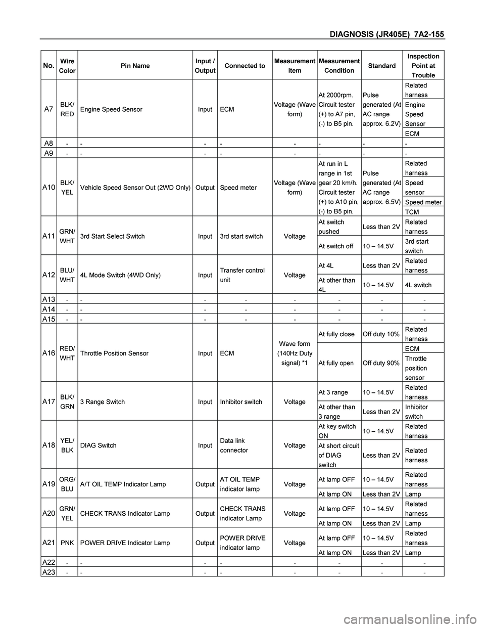
No. Wire
Color Pin Name Input /
OutputConnected toMeasurement
Item Measurement
Condition StandardInspection
Point at
Trouble
Related
harness
Engine
Speed
Sensor A7 BLK/
RED Engine Speed Sensor Input ECM Voltage (Wave
form) At 2000rpm.
Circuit tester
(+) to A7 pin,
(-) to B5 pin. Pulse
generated (At
AC range
approx. 6.2V)
ECM
A8 - - - - - - - -
A9 - - - - - - - -
Related
harness
Speed
sensor
Speed meter
A10 BLK/
YEL Vehicle Speed Sensor Out (2WD Only) Output Speed meter Voltage (Wave
form) At run in L
range in 1st
gear 20 km/h.
Circuit tester
(+) to A10 pin,
(-) to B5 pin. Pulse
generated (At
AC range
approx. 6.5V)
TCM
At switch
pushed Less than 2VRelated
harness
A11 GRN/
WHT 3rd Start Select Switch Input 3rd start switch Voltage
At switch off 10 – 14.5V 3rd start
switch
At 4L Less than 2VRelated
harness
A12 BLU/
WHT 4L Mode Switch (4WD Only) InputTransfer control
unit Voltage
At other than
4L 10 – 14.5V 4L switch
A13 - - - - - - - -
A14 - - - - - - - -
A15 - - - - - - - -
At fully close Off duty 10%Related
harness
ECM A16 RED/
WHT Throttle Position Sensor Input ECM Wave form
(140Hz Duty
signal) *1
At fully open Off duty 90%Throttle
position
sensor
At 3 range 10 – 14.5V Related
harness
A17 BLK/
GRN 3 Range Switch Input Inhibitor switch Voltage
At other than
3 range Less than 2VInhibitor
switch
At key switch
ON 10 – 14.5V Related
harness
A18 YEL/
BLK DIAG Switch InputData link
connector Voltage
At short circuit
of DIAG
switch Less than 2VRelated
harness
At lamp OFF 10 – 14.5V Related
harness A19 ORG/
BLU A/T OIL TEMP Indicator Lamp OutputAT OIL TEMP
indicator lamp Voltage
At lamp ON Less than 2V Lamp
At lamp OFF 10 – 14.5V Related
harness A20 GRN/
YEL CHECK TRANS Indicator Lamp OutputCHECK TRANS
indicator Lamp Voltage
At lamp ON Less than 2V Lamp
At lamp OFF 10 – 14.5V Related
harness A21 PNK POWER DRIVE Indicator Lamp OutputPOWER DRIVE
indicator lamp Voltage
At lamp ON Less than 2V Lamp
A22 - - - - - - - -
A23 - - - - - - - -
Page 4150 of 4264

7A2-158 DIAGNOSIS (JR405E)
No. Wire
Color Pin Name Input /
OutputConnected toMeasurement
Item Measurement
Condition StandardInspection
Point at
Trouble
At key switch
ON 10 – 14.5V Related
harness
B24 WHT V ign (Ignition Power Supply) Input Key switch Voltage
At Key switch
OFF Less than 2V Fuse
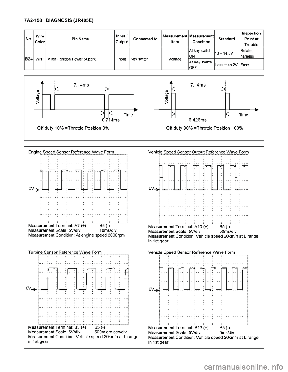
7.14ms 7.14ms
Time Time
0.714ms 6.426ms
Voltage
Off duty 10% =Throttle Position 0%
Voltage
Off duty 90% =Throttle Position 100%
Engine Speed Sensor Reference Wave Form
Measurement Terminal: A7 (+) B5 (-)
Measurement Scale: 5V/div 10ms/div
Measurement Condition: At engine speed 2000rpm
0V
Vehicle Speed Sensor Output Reference Wave Form
Measurement Terminal: A10 (+) B5 (-)
Measurement Scale: 5V/div 50ms/div
Measurement Condition: Vehicle speed 20km/h at L range
in 1st gear
0V
Turbine Sensor Reference Wave Form
Measurement Terminal: B3 (+) B5 (-)
Measurement Scale: 5V/div 500micro sec/div
Measurement Condition: Vehicle speed 20km/h at L range
in 1st gear
0V
Vehicle Speed Sensor Reference Wave Form
Measurement Terminal: B13 (+) B5 (-)
Measurement Scale: 5V/div 5ms/div
Measurement Condition: Vehicle speed 20km/h at L range
in 1st gear
0V
Page 4153 of 4264

ON-VEHICLE SERVICE (JR405E) 7A3-1
SECTION 7A3
ON-VEHICLE SERVICE (JR405E)
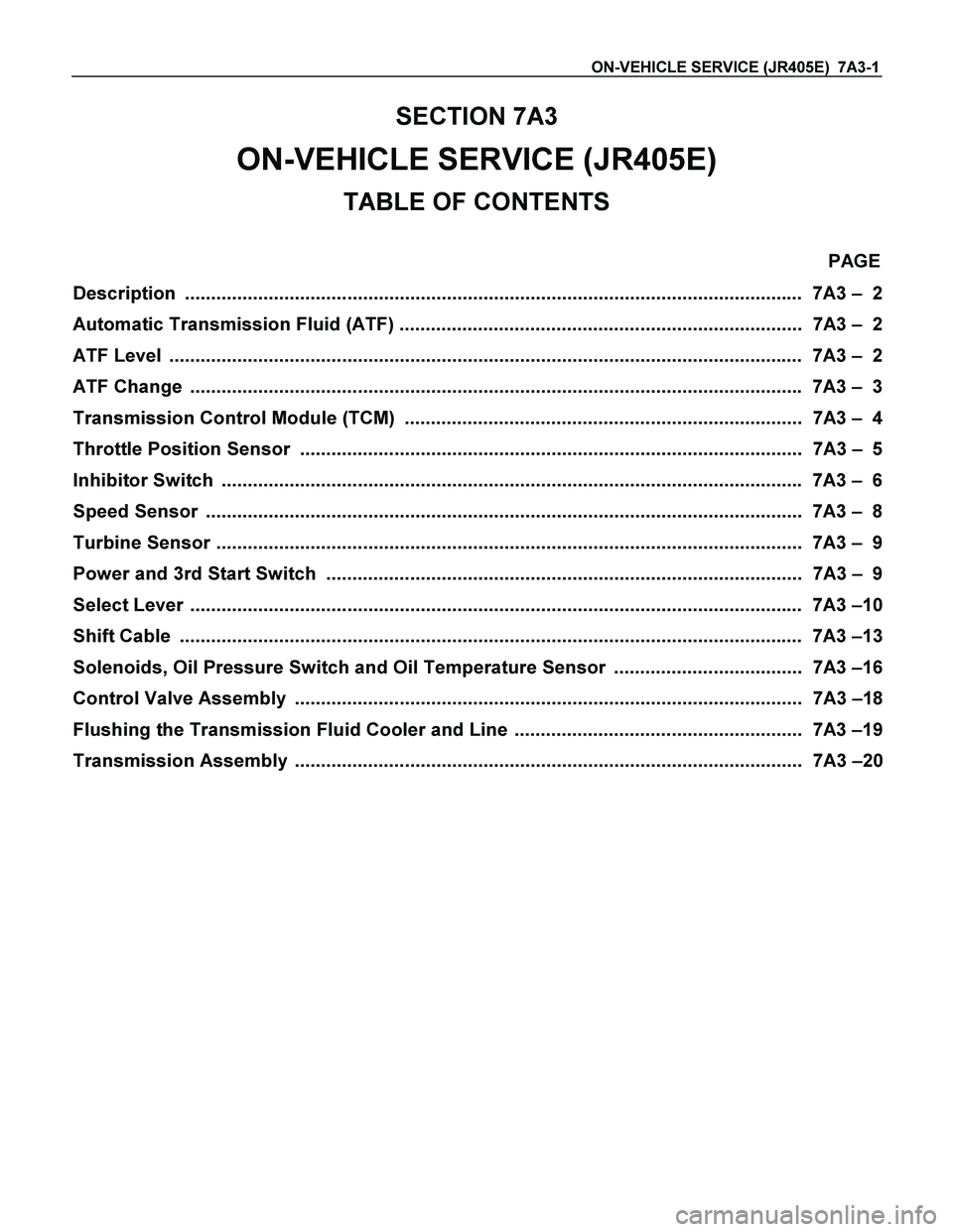
TABLE OF CONTENTS
PAGE
Description ...................................................................................................................... 7A3 – 2
Automatic Transmission Fluid (ATF) ............................................................................. 7A3 – 2
ATF Level ......................................................................................................................... 7A3 – 2
ATF Change ..................................................................................................................... 7A3 – 3
Transmission Control Module (TCM) ............................................................................ 7A3 – 4
Throttle Position Sensor ................................................................................................ 7A3 – 5
Inhibitor Switch ............................................................................................................... 7A3 – 6
Speed Sensor .................................................................................................................. 7A3 – 8
Turbine Sensor ................................................................................................................ 7A3 – 9
Power and 3rd Start Switch ........................................................................................... 7A3 – 9
Select Lever ..................................................................................................................... 7A3 –10
Shift Cable ....................................................................................................................... 7A3 –13
Solenoids, Oil Pressure Switch and Oil Temperature Sensor .................................... 7A3 –16
Control Valve Assembly ................................................................................................. 7A3 –18
Flushing the Transmission Fluid Cooler and Line ....................................................... 7A3 –19
Transmission Assembly ................................................................................................. 7A3 –20
Page 4157 of 4264
ON-VEHICLE SERVICE (JR405E) 7A3-5
THROTTLE POSITION SENSOR
1
P1010052
The throttle position sensor (1) is fitted on the throttle
valve body.
Adjust
1. Turn the starter switch to the “ON ” position.
2. Measure the voltage between TPS connecto
r
terminals (B) (output) and (A) (ground).
Note:
� Do not remove the sensor connector.
� Make sure that power source (5.0 � 0.01 V) is
measured between TPS connector terminals (C) and
(A) before measurement at step 2.
Standard voltage :
Throttle Angle TPS
Idling (0%) 0.2 - 0.3 V
WOT (100%) 3.4 – 4.1 V
RTW37ASH0013
3. If the reading is beyond the specified value, loosen
the throttle position sensor fixing bolts, and turn i
t
right or left, so that the specified output voltage be
obtained.
After adjusting, tighten the throttle position sensor
fixing screws (2).
826R300013